
2015 Malibu Dual Battery Control Module
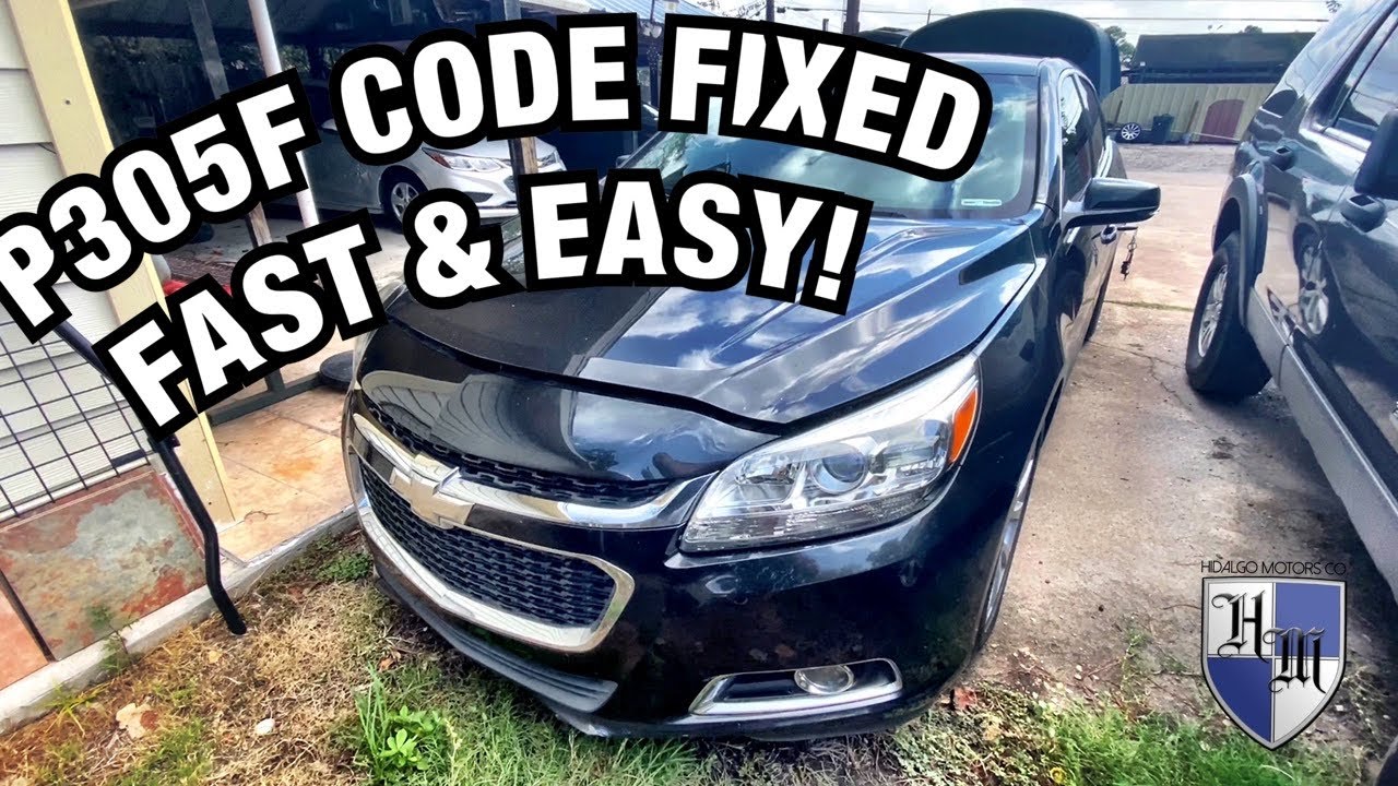
The 2015 Chevrolet Malibu, like many modern vehicles, incorporates sophisticated power management systems to enhance efficiency and reliability. A key component of this system, often overlooked but critically important, is the Dual Battery Control Module (DBCM). While not a true dual-battery setup like those found in heavy-duty trucks or off-road vehicles, the Malibu utilizes a clever approach to manage power distribution between the main starting battery and an auxiliary battery, sometimes referred to as an 'absorbent glass mat' (AGM) battery. This article delves into the functionality, components, and operational principles of the 2015 Malibu's DBCM, providing a technical overview for enthusiasts and amateur engineers.
Overview of the Dual Battery System
Before diving into the specifics of the DBCM, it's essential to understand the rationale behind this type of system. Modern vehicles are equipped with an ever-increasing array of electronic components, including infotainment systems, power seats, advanced driver-assistance systems (ADAS), and stop-start technology. These systems demand a stable and consistent power supply. The Malibu's dual-battery system is designed to meet these demands, improve fuel economy, and enhance battery lifespan.
The primary battery is responsible for starting the engine and providing power during initial startup. The auxiliary battery, on the other hand, primarily supports the vehicle's electrical loads when the engine is off, especially during auto stop-start events. This arrangement reduces the strain on the main battery, preventing premature degradation and ensuring reliable engine starts. Furthermore, the auxiliary battery can provide a backup power source for essential functions if the main battery fails.
Components of the Dual Battery System
The 2015 Malibu's dual battery system comprises several key components working in concert:
- Main Battery: Typically a standard lead-acid battery, responsible for engine cranking.
- Auxiliary Battery: Usually an AGM battery known for its deep-cycle capabilities and ability to handle frequent charge and discharge cycles, ideal for stop-start systems.
- Dual Battery Control Module (DBCM): The heart of the system, managing charging, discharging, and isolation of the two batteries.
- Current Sensors: Located on both battery terminals, these sensors provide real-time data on battery current and voltage to the DBCM.
- Wiring Harness and Connectors: High-quality wiring and connectors ensure reliable power transfer and communication between components.
Detailed Look at the Dual Battery Control Module (DBCM)
The DBCM is an electronic control unit (ECU) that acts as the brain of the dual-battery system. Its primary functions are to:
- Monitor Battery Voltage and Current: The DBCM constantly monitors the voltage and current of both batteries using data from the current sensors.
- Control Charging: Based on battery state-of-charge (SOC) and vehicle operating conditions, the DBCM regulates the charging current to both batteries, preventing overcharging and ensuring optimal battery health.
- Manage Load Distribution: The DBCM determines which battery provides power to the vehicle's electrical loads, prioritizing the auxiliary battery during engine-off periods.
- Isolate Batteries: The DBCM can isolate the main battery from the auxiliary battery under certain conditions, such as low voltage or charging faults, to prevent damage and maintain system integrity.
- Communicate with the Vehicle's ECU: The DBCM communicates with the vehicle's main ECU via the Controller Area Network (CAN) bus, sharing data on battery status, system faults, and operating conditions.
Internal Architecture of the DBCM
While specific internal schematics are proprietary, the DBCM typically consists of the following key components:
- Microcontroller: A powerful microcontroller processes sensor data, executes control algorithms, and manages communication with other vehicle systems.
- Analog-to-Digital Converters (ADCs): ADCs convert analog signals from the current and voltage sensors into digital data for processing by the microcontroller.
- Power MOSFETs (Metal-Oxide-Semiconductor Field-Effect Transistors): High-current MOSFETs are used as switches to control the flow of charging current and isolate batteries.
- Gate Drivers: Gate drivers amplify the control signals from the microcontroller to drive the MOSFETs effectively.
- DC-DC Converter (Optional): In some designs, a DC-DC converter may be included to optimize the charging voltage for the auxiliary battery.
- CAN Transceiver: A CAN transceiver enables communication with the vehicle's CAN bus.
- Protection Circuitry: Overvoltage, overcurrent, and thermal protection circuits safeguard the DBCM and batteries from damage.
Operational Modes and Logic
The DBCM operates in various modes, depending on the vehicle's operating conditions:
- Engine Running (Charging Mode): When the engine is running, the alternator charges both batteries. The DBCM regulates the charging current based on the SOC of each battery, prioritizing the battery with the lower SOC.
- Engine Off (Stop-Start Event): During a stop-start event, the engine shuts off, and the auxiliary battery provides power to the vehicle's electrical loads. The DBCM monitors the auxiliary battery voltage and restarts the engine if the voltage drops below a predetermined threshold.
- Engine Off (Parked): When the vehicle is parked, the DBCM continues to monitor battery voltage. It may periodically activate a trickle charge to maintain battery health, especially if the vehicle is equipped with parasitic loads (e.g., alarm system).
- Fault Mode: If the DBCM detects a fault, such as low battery voltage, overcurrent, or communication error, it enters fault mode. In this mode, it may isolate the batteries, disable the stop-start system, and illuminate a warning light on the instrument panel.
Troubleshooting and Diagnostics
Diagnosing issues with the DBCM or the dual-battery system typically involves using a scan tool to read diagnostic trouble codes (DTCs) from the vehicle's ECU. Common DTCs related to the DBCM may indicate:
- Low battery voltage
- High battery voltage
- Communication errors
- Current sensor faults
- DBCM internal faults
In addition to reading DTCs, a thorough diagnostic procedure may involve:
- Visual Inspection: Inspecting the batteries, wiring, and connectors for damage or corrosion.
- Voltage Testing: Measuring battery voltage with a multimeter to verify battery condition.
- Current Testing: Measuring battery current with a current clamp to identify excessive parasitic draw.
- Load Testing: Performing a load test on each battery to assess its ability to deliver current under load.
- Component Testing: Using a multimeter or oscilloscope to test the DBCM's input and output signals.
Important Note: Working with automotive electrical systems can be dangerous. Always disconnect the battery negative terminal before performing any electrical work. Consult a qualified technician if you are not comfortable performing these procedures.
Conclusion
The 2015 Malibu's Dual Battery Control Module is a sophisticated system designed to enhance fuel economy, improve battery lifespan, and ensure reliable power delivery to the vehicle's electrical components. Understanding its functionality, components, and operational principles can be valuable for enthusiasts and amateur engineers alike. While troubleshooting and repair should ideally be left to qualified professionals, a basic understanding of the DBCM can aid in identifying potential problems and making informed decisions about vehicle maintenance.