3 Wire Oil Pressure Switch Wiring Diagram
The ubiquitous oil pressure switch. It's a seemingly simple component, yet it plays a critical role in safeguarding your engine. While the single-wire, "idiot light" version is well understood, the 3-wire oil pressure switch introduces a layer of sophistication, providing not only a warning light but also, crucially, an analog signal for the engine control unit (ECU). Let's dive deep into the wiring and functionality of these essential sensors.
Understanding the Need for a 3-Wire System
Before dissecting the wiring diagram, it's important to appreciate why a 3-wire system exists. Early vehicles relied on a simple on/off switch connected to an oil pressure warning light. If the pressure dropped below a certain threshold (typically around 5-7 PSI), the switch closed, completing the circuit and illuminating the light. This system, while functional, offered no intermediate information. It was either "good" or "bad."
Modern engines, with their sophisticated ECUs, demand more granular data. The ECU uses sensor data from various sources to optimize fuel injection, ignition timing, and other parameters. Knowing the actual oil pressure, rather than simply a "low" indication, allows the ECU to make more informed decisions, potentially preventing engine damage or triggering preemptive maintenance alerts.
The 3-wire oil pressure switch bridges this gap. It provides both a traditional on/off signal for a warning light and a variable voltage signal proportional to the oil pressure. This dual functionality is what sets it apart.
The 3-Wire Oil Pressure Switch Wiring Diagram: A Deep Dive
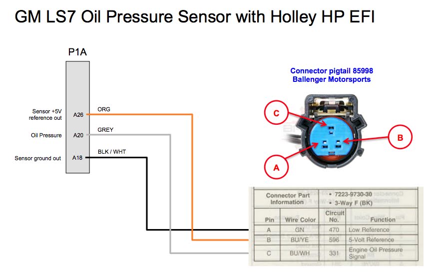
A typical 3-wire oil pressure switch wiring diagram will feature the following connections:
1. Power (Vref or VCC)
This wire supplies a regulated voltage (typically 5 volts, although some systems may use other voltages – always refer to the specific vehicle's wiring diagram) to the sensor. This voltage acts as a reference for the sensor's internal circuitry. The ECU provides this power. Think of it as the "fuel" that powers the sensor's ability to measure pressure.
Important Note: Using the incorrect voltage can damage the sensor or provide inaccurate readings. Always verify the correct voltage specification for your particular sensor and vehicle.
2. Ground (GND)
This wire provides the electrical ground connection for the sensor. It's essential for completing the circuit and allowing the sensor to function correctly. A clean, solid ground connection is crucial for accurate readings. A poor ground can introduce noise into the signal, leading to erratic or unreliable oil pressure data. Often this ground will be shared by other sensors on the engine.
3. Signal (Vout)
This wire carries the analog voltage signal back to the ECU. The voltage on this wire varies proportionally to the oil pressure. When the oil pressure is low, the voltage will be low; as the oil pressure increases, the voltage increases. The ECU reads this voltage and interprets it as a specific oil pressure value.
The relationship between the voltage and pressure is critical. This relationship is defined by the sensor's transfer function, often expressed as a graph or equation. This function will be available in the manufacturer's documentation for the specific sensor model. For example, a sensor might output 0.5V at 0 PSI and 4.5V at 100 PSI. The ECU uses this transfer function to convert the voltage reading into a meaningful oil pressure value.
How It Works: Internal Sensor Operation
Inside the 3-wire oil pressure switch is a pressure-sensitive element, typically a diaphragm or a Bourdon tube. This element deforms under pressure. This deformation is then translated into an electrical signal using one of several technologies:
- Piezoresistive Sensor: This type utilizes a strain gauge (a resistor whose resistance changes with strain) bonded to the pressure-sensitive element. As the element deforms, the strain gauge's resistance changes. This change in resistance alters the voltage output, creating the analog signal.
- Capacitive Sensor: This type uses a variable capacitor, where the capacitance changes with pressure. The pressure-sensitive element moves one plate of the capacitor, altering the distance between the plates and thus the capacitance. An electronic circuit converts this change in capacitance into a voltage signal.
Regardless of the specific technology, the principle remains the same: the pressure-sensitive element transforms the mechanical pressure into a measurable electrical signal.
Troubleshooting a 3-Wire Oil Pressure Switch
If you suspect a problem with your 3-wire oil pressure switch, here are some troubleshooting steps:
- Check the Wiring: Inspect the wiring and connectors for damage, corrosion, or loose connections. A visual inspection is often the first and most effective step. Ensure all connections are clean and secure.
- Verify the Power Supply: Use a multimeter to confirm that the sensor is receiving the correct voltage (typically 5 volts) on the Vref/VCC wire. If the voltage is missing or incorrect, investigate the ECU and associated wiring.
- Check the Ground: Use a multimeter to verify that the ground wire has a good connection to the vehicle's chassis. A poor ground can cause all sorts of issues.
- Measure the Signal Voltage: With the engine running, use a multimeter to measure the voltage on the signal wire. The voltage should vary with engine speed and oil pressure. Compare the measured voltage to the sensor's transfer function to verify that the sensor is operating correctly.
- Scan for Diagnostic Trouble Codes (DTCs): Use an OBD-II scanner to check for any DTCs related to the oil pressure sensor. These codes can provide valuable clues about the nature of the problem.
- Inspect Oil Pressure Mechanically: If electrical tests are inconclusive, verify actual oil pressure with a mechanical gauge. Install a gauge to the engine and compare its reading to what the ECU reports. Discrepancies point to sensor failure.
Caution: Always disconnect the negative battery terminal before working on any electrical components in your vehicle.
Common Failure Modes
3-wire oil pressure switches, like any sensor, are prone to certain failure modes:
- Drifting: The sensor's output voltage may drift over time, leading to inaccurate readings. This can be caused by aging of the internal components.
- Sticking: The pressure-sensitive element may become stuck, resulting in a fixed voltage output, regardless of the actual oil pressure.
- Open Circuit: One of the internal wires may break, resulting in a complete loss of signal.
- Short Circuit: One of the wires may short to ground or to another wire, causing incorrect readings or damaging the ECU.
- Contamination: Oil contaminants can foul the pressure sensor and lead to incorrect readings or sensor failure.
Ultimately, understanding the 3-wire oil pressure switch wiring diagram and its underlying principles empowers you to diagnose and troubleshoot problems effectively, ensuring the longevity and performance of your engine. While this information provides a solid foundation, always refer to your vehicle's specific service manual for detailed instructions and wiring diagrams specific to your application. Safety first!
Disclaimer: This information is for educational purposes only and should not be considered a substitute for professional advice. Working on automotive electrical systems can be dangerous. Always exercise caution and follow proper safety procedures.