
Evap System Purge Control Valve A Circuit
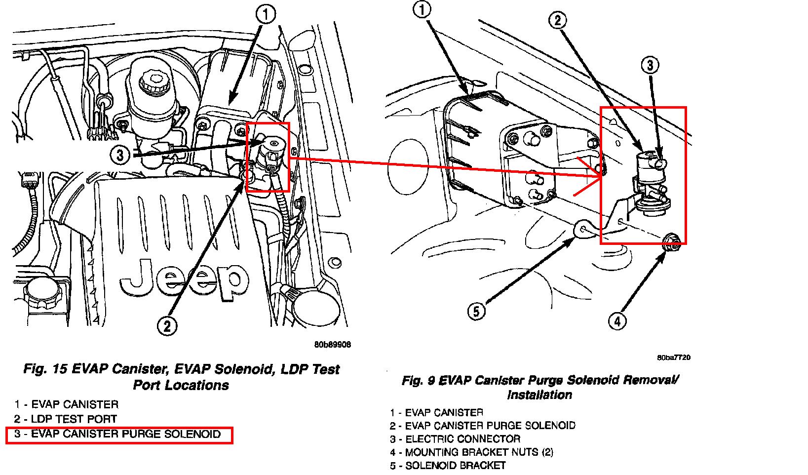
The Evaporative Emission (EVAP) control system is a crucial component of modern vehicles, designed to prevent harmful fuel vapors from escaping into the atmosphere. At the heart of this system lies the Purge Control Valve (PCV), a seemingly simple device with a vital role. When a diagnostic trouble code (DTC) like "Evap System Purge Control Valve A Circuit" pops up, it's a signal that something is amiss with this valve or its associated circuitry, demanding immediate attention. This article will delve into the intricacies of the PCV "A" circuit, exploring its function, common failure modes, and diagnostic procedures.
Understanding the Evap System
Before diving into the specifics of the PCV, let's briefly recap the EVAP system's operation. Fuel vapors generated in the fuel tank are routed to a charcoal canister, where they are stored. When the engine is running and certain conditions are met (engine temperature, speed, etc.), the engine control unit (ECU) activates the Purge Control Valve. This valve opens, allowing vacuum from the intake manifold to draw the stored fuel vapors from the charcoal canister into the engine, where they are burned during normal combustion. This prevents raw fuel vapors from venting to the environment, reducing emissions and improving fuel economy.
The Purge Control Valve's Role
The Purge Control Valve is typically a solenoid-operated valve, meaning it uses an electromagnetic coil to open and close. The ECU controls the valve's duty cycle (the percentage of time it's open), regulating the flow of fuel vapor into the engine. A faulty PCV can lead to various problems, including poor fuel economy, rough idling, and emissions test failures. The "A" designation in the DTC "Evap System Purge Control Valve A Circuit" indicates that this is the primary PCV in a vehicle with multiple such valves, or that it is the only PCV in the system.
"A Circuit" Explained
The phrase "A Circuit" specifically refers to the electrical circuit that controls the PCV. This circuit includes the wiring, connectors, the solenoid within the valve itself, and the ECU's driver circuit responsible for powering the valve. A problem within this circuit can manifest in several ways, leading to the aforementioned symptoms. Common causes for a "Purge Control Valve A Circuit" DTC include:
- Open Circuit: A break in the wiring preventing current from reaching the valve. This could be due to a damaged wire, a corroded connector, or a faulty solenoid coil.
- Short to Ground: The wire carrying power to the valve is making contact with the vehicle's chassis, creating a short circuit. This can damage the ECU's driver circuit.
- Short to Voltage: The wire carrying power to the valve is making contact with another wire carrying voltage, potentially causing the valve to stay open constantly.
- Faulty Purge Control Valve: The solenoid within the valve itself has failed, preventing it from opening or closing properly.
- Faulty ECU: Although less common, the ECU's driver circuit responsible for controlling the PCV may be defective.
Diagnosing the "A Circuit" DTC
Diagnosing a "Purge Control Valve A Circuit" DTC requires a systematic approach. Start by visually inspecting the wiring and connectors associated with the PCV. Look for signs of damage, corrosion, or loose connections. Use a multimeter to check for voltage and ground at the valve's connector with the ignition on. If voltage and ground are present, the issue likely lies within the valve itself.
To further isolate the problem, perform the following tests:
- Continuity Test: Disconnect the PCV and use a multimeter to check the continuity of the wiring between the valve's connector and the ECU. This will identify any open circuits.
- Resistance Test: Measure the resistance of the PCV solenoid coil. A reading outside the manufacturer's specifications indicates a faulty valve.
- Activation Test: Using a scan tool, attempt to activate the PCV. Listen for a clicking sound, indicating that the solenoid is attempting to operate. If there is no sound, there is a problem with either the valve or the wiring.
Remember to consult the vehicle's service manual for specific diagnostic procedures and wiring diagrams. Always disconnect the negative battery cable before working on electrical circuits to prevent accidental shorts.
Repairing the "A Circuit"
The repair strategy depends on the root cause of the problem. Damaged wiring can be repaired by splicing in new sections of wire and properly insulating the connections. Corroded connectors should be cleaned or replaced. A faulty PCV should be replaced with a new or remanufactured unit. In rare cases, a faulty ECU may need to be replaced or reprogrammed. After completing the repair, clear the DTC and verify that the system is functioning properly by monitoring the PCV's operation with a scan tool.
A thorough understanding of the Evap System and the Purge Control Valve's function is crucial for diagnosing and repairing these "A Circuit" related issues effectively. By following a systematic diagnostic approach and utilizing the appropriate tools and resources, automotive professionals and enthusiasts alike can successfully resolve these problems and keep vehicles running cleanly and efficiently.