
How To Check Dc Voltage With A Multimeter
Ah, electricity. That invisible force powering our modern lives. While you can't see it flowing, you can measure it, and one of the most fundamental measurements is DC voltage. Knowing how to check DC voltage with a multimeter is a crucial skill for anyone dabbling in electronics, troubleshooting car electrical systems, or even just wanting to understand how that wall wart powers your favorite gadget. Think of it as using a dipstick to check the "oil level" of your circuits.
Understanding the Tools and Concepts
Before we dive into the how-to, let's lay the groundwork. What is DC voltage, and what's a multimeter anyway?
What is DC Voltage?
DC, or Direct Current, is electricity that flows in one direction. Think of a battery. It has a positive (+) and a negative (-) terminal, and electrons relentlessly flow from the negative to the positive. This consistent flow creates a voltage difference, the electrical potential that drives current through a circuit. Voltage, measured in Volts (V), is essentially the "pressure" that pushes the electrons along. Higher voltage means more "pressure," and potentially more current flow (depending on the resistance in the circuit).
The Multimeter: Your Electrical Swiss Army Knife
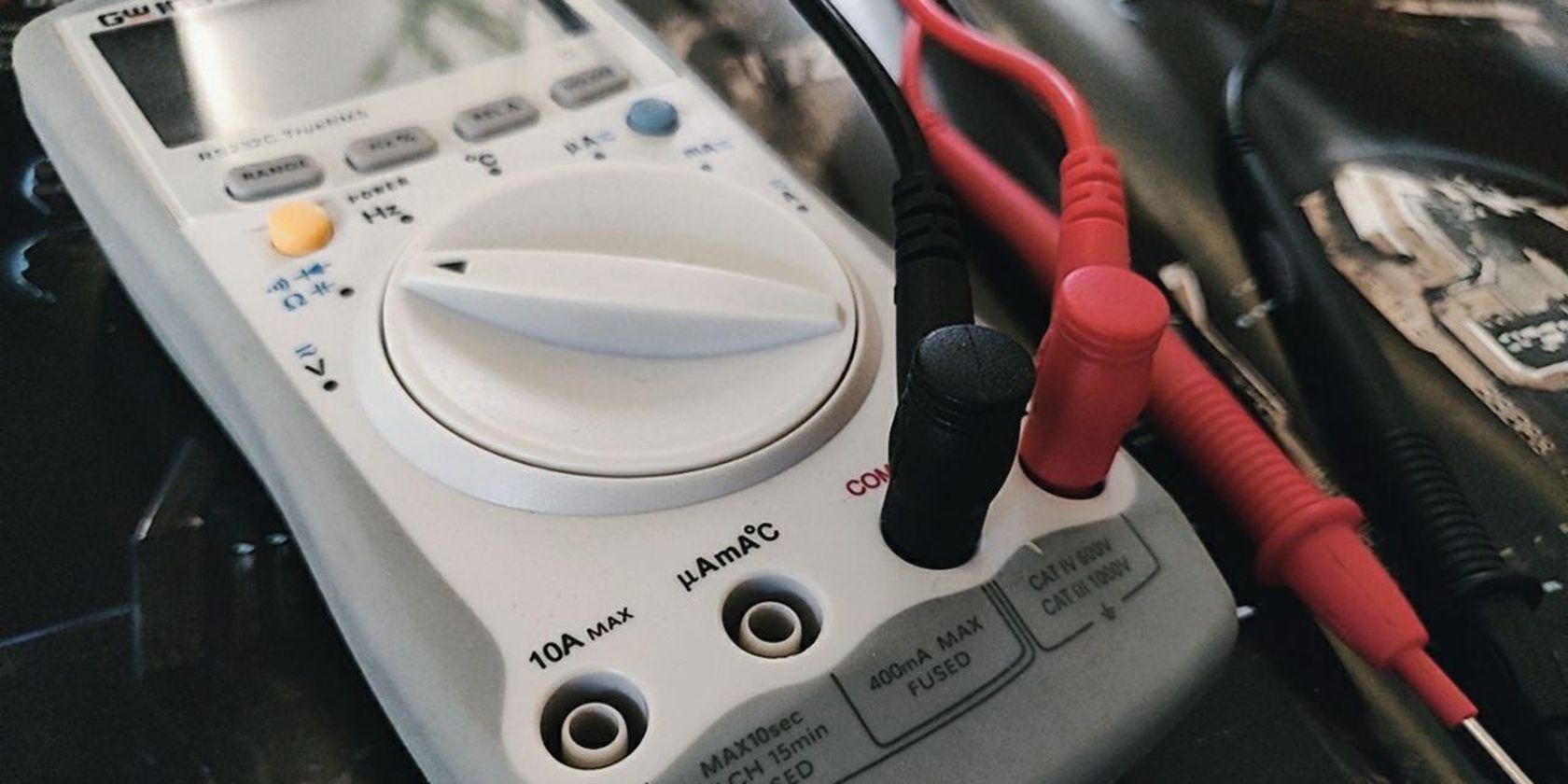
A multimeter is a versatile instrument capable of measuring voltage, current, and resistance. Some even handle other parameters like capacitance and frequency. For our purposes, we'll focus on its DC voltage measuring capabilities. Your multimeter will have:
- A Display: Shows the measurement readings.
- A Function/Range Selector Knob: Allows you to choose what you're measuring (DC voltage, AC voltage, current, resistance, etc.) and the appropriate measurement range.
- Test Leads: Typically red (positive) and black (negative). These connect the multimeter to the circuit you're testing.
- Input Jacks: Where you plug in the test leads. Usually, there's a common (COM) jack for the black lead and a VΩmA jack for the red lead (used for voltage, resistance, and small current measurements). Some multimeters have a separate jack for measuring high currents (typically labeled "10A" or "20A").
It's crucial to understand these components to use the multimeter safely and effectively.
Step-by-Step Guide: Measuring DC Voltage
Now, let's get down to the practical part. Here's a step-by-step guide to measuring DC voltage:
- Safety First! Always exercise caution when working with electricity. Even low voltages can deliver a surprising jolt. Make sure the circuit you're testing is de-energized if possible. If not, be extremely careful not to short-circuit anything. Do not touch exposed wires or components while the circuit is powered.
- Connect the Test Leads: Plug the black test lead into the COM (common) jack and the red test lead into the VΩmA jack.
- Select the DC Voltage Function: Turn the function/range selector knob to the DC voltage (usually marked as "V" with a straight line above or next to it). Some multimeters have both manual and auto-ranging settings.
- Manual Ranging: You need to select the voltage range that's higher than the voltage you expect to measure. For example, if you're measuring a 12V battery, select a range like 20V or 50V. If you're unsure of the voltage, start with the highest range and work your way down. Choosing a range too low will overload the meter and potentially damage it.
- Auto-Ranging: The multimeter automatically selects the appropriate range. This is generally easier for beginners. Just select the DC voltage function (usually just "V" with a straight line).
- Connect to the Circuit: This is where you make the actual measurement.
- Parallel Connection: Voltage is always measured in parallel with the component or circuit you're testing. This means you place the test leads across the component, not in series with it.
- Polarity Matters: The red test lead should be connected to the positive (+) side of the circuit, and the black test lead to the negative (-) side (or ground). Reversing the polarity will usually result in a negative reading on the display, but it won't damage the meter (in most cases).
- Good Contact: Ensure the test leads make good, solid contact with the circuit. Poor contact will result in inaccurate readings. Consider using alligator clips or test probes for easier and more reliable connections.
- Read the Display: Once the test leads are connected, the display will show the DC voltage reading. Note the units (Volts, mV, etc.). If you're using a manual-ranging meter and the display shows "OL" (overload) or a similar indication, it means the selected range is too low. Increase the range until you get a valid reading.
- Interpret the Results: The voltage reading tells you the potential difference between the two points you connected the test leads to. This can help you diagnose problems, verify component functionality, or simply understand the behavior of the circuit.
Troubleshooting and Common Mistakes
Even with careful execution, problems can arise. Here are some common mistakes and troubleshooting tips:
- Incorrect Function Selection: Ensure the multimeter is set to DC voltage (V with a straight line). Accidentally measuring voltage in resistance mode (Ω) or current mode (A) can lead to inaccurate readings or even damage the meter.
- Incorrect Range Selection (Manual Ranging): As mentioned before, selecting too low a range will overload the meter. Start with the highest range and work your way down.
- Poor Contact: Dirty or corroded test leads or circuit connections can prevent accurate readings. Clean the leads and connections with a suitable cleaner.
- Dead Battery in Multimeter: A low battery in the multimeter can cause erratic or inaccurate readings. Replace the battery if necessary.
- Blown Fuse in Multimeter: Multimeters often have internal fuses to protect them from overcurrent. If you're measuring current and the meter suddenly stops working, the fuse may be blown. Consult your multimeter's manual for instructions on replacing the fuse.
- Floating Ground: In some circuits, the "ground" may not be a true ground reference. This can lead to unstable or inaccurate voltage readings. Use a known good ground point for your measurements.
- Electrical Noise: Some circuits can be noisy, with rapidly fluctuating voltages. This can make it difficult to get a stable reading. Use a multimeter with a filtering function or observe the reading over a longer period to get an average value.
Beyond the Basics: Advanced Techniques
Once you're comfortable with the basics, you can explore more advanced techniques:
- Measuring Voltage Drop: Voltage drop is the voltage lost across a component due to its resistance. Measuring voltage drop can help you identify faulty components or wiring problems.
- Checking for Shorts: By measuring the voltage across a shorted circuit, you can confirm the presence of a short circuit condition.
- Using a Logic Probe: A logic probe is a specialized tool for quickly checking the logic levels (high or low) of digital circuits. It can be a valuable complement to a multimeter.
Mastering the art of measuring DC voltage with a multimeter is a valuable skill that will empower you to troubleshoot electrical problems, understand circuit behavior, and ultimately become a more confident and capable electronics enthusiast. Remember to always prioritize safety, double-check your connections, and consult your multimeter's manual for specific instructions. Happy measuring!