
How To Check Voltage Drop With Multimeter
Voltage drop is a critical concept in automotive electrical systems, often overlooked but crucial for diagnosing a wide range of problems, from dim headlights to intermittent sensor failures. Essentially, voltage drop is the loss of electrical potential (voltage) as current flows through a conductor or circuit. A significant voltage drop indicates excessive resistance, which can hinder the proper operation of electrical components. This article will guide you through the process of checking voltage drop using a multimeter, enabling you to diagnose and repair electrical issues effectively.
Understanding Voltage Drop and its Significance
Before diving into the testing procedure, it's important to grasp the concept of voltage drop and why it matters. Imagine a garden hose: if there's a kink in the hose, water flow is restricted, and pressure drops at the nozzle. Similarly, in an electrical circuit, excessive resistance (caused by corrosion, loose connections, or damaged wiring) restricts current flow, leading to a drop in voltage across that resistance. This means less voltage is available for the component meant to be powered.
Acceptable voltage drop varies depending on the circuit and component. Generally, the following guidelines apply:
- Starting circuit: No more than 0.5V drop on the positive side and 0.2V on the ground side.
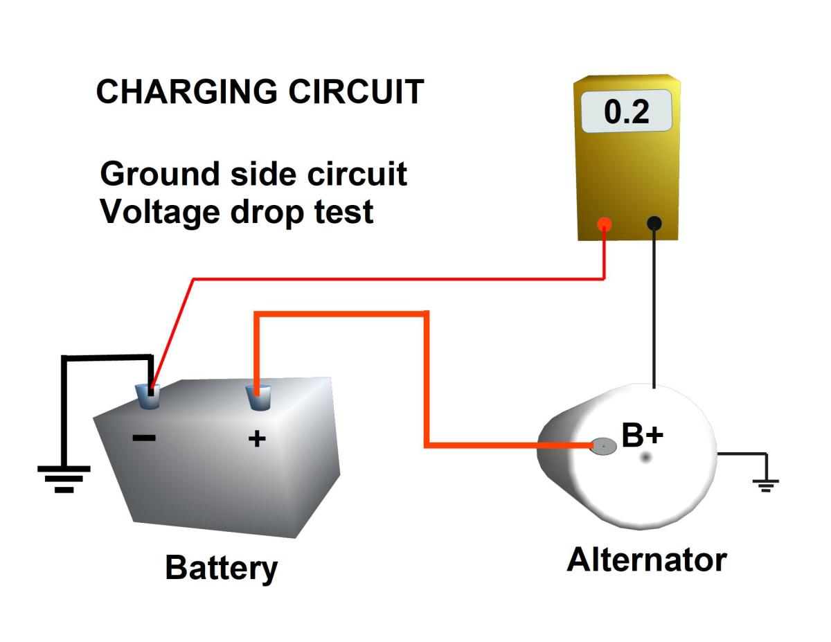
- Charging circuit: No more than 0.5V drop on either the positive or ground side.
- Lighting circuits: No more than 0.5V drop.
- Other circuits: No more than 0.3V drop.
Exceeding these limits suggests a problem that needs addressing.
Tools Required
To perform a voltage drop test, you'll need the following:
- A quality digital multimeter (DMM): Ensure it's capable of reading DC voltage accurately.
- Test leads with sharp probes: For piercing insulation if necessary (use sparingly).
- Wiring diagram: To identify circuit components and wiring routes.
- Safety glasses and gloves: For personal protection.
Procedure: Checking Voltage Drop with a Multimeter
Follow these steps to accurately measure voltage drop:
- Safety First: Ensure the vehicle is safely parked, the engine is off, and the parking brake is engaged. Disconnect the negative battery terminal if you are working on a high-current circuit.
- Identify the Circuit: Use a wiring diagram to locate the circuit you want to test and identify the points where you'll measure voltage.
- Prepare the Multimeter: Set your multimeter to the DC voltage setting (usually denoted by "VDC" or "DCV"). Select the appropriate voltage range. If unsure, start with the highest range and lower it until you get a clear reading.
- Connect the Multimeter: Connect the multimeter's test leads in parallel with the section of the circuit you want to test while the circuit is under load. This is the key – the circuit must be operating for a voltage drop to be measurable.
- Place the red (positive) lead at the beginning of the circuit segment you are testing (closest to the power source).
- Place the black (negative) lead at the end of the circuit segment you are testing (closest to the component).
- Load the Circuit: Activate the circuit. For example, if testing a headlight circuit, turn on the headlights. If testing a motor circuit, activate the motor. The circuit *must* be drawing current for the test to be valid.
- Read the Voltage Drop: Observe the voltage reading on the multimeter. This is the voltage drop across that segment of the circuit.
- Interpret the Results: Compare the measured voltage drop to the acceptable limits for that specific circuit. If the reading exceeds the acceptable limit, there's excessive resistance in that section of the circuit.
- Isolate the Problem: If a significant voltage drop is detected, systematically test smaller sections of the circuit to pinpoint the exact location of the resistance. This could involve testing individual wires, connectors, switches, or components.
Real-World Example: Diagnosing a Dim Headlight
Let's say a customer complains about a dim headlight. You suspect excessive voltage drop in the headlight circuit.
- Locate the headlight circuit wiring diagram.
- With the headlight switched on, place the red lead of the multimeter on the battery positive terminal and the black lead on the positive terminal of the headlight connector.
- If the voltage drop exceeds 0.5V, there's excessive resistance somewhere in that path.
- Next, test the voltage drop across the headlight switch. If the switch shows a significant drop, it's likely faulty.
- If the switch is okay, check the wiring and connectors between the battery and the headlight, looking for corrosion or loose connections.
Common Causes of Voltage Drop
Several factors can contribute to voltage drop:
- Corrosion: Oxidation on terminals and connectors increases resistance.
- Loose Connections: Poorly secured connections create resistance and heat.
- Damaged Wiring: Frayed or broken wires reduce current-carrying capacity.
- Faulty Switches or Relays: Worn contacts within switches and relays increase resistance.
- Undersized Wiring: Using wiring that is too small for the current draw can cause excessive voltage drop.
Conclusion
Checking voltage drop with a multimeter is a powerful diagnostic technique for identifying electrical problems in automotive systems. By understanding the principles of voltage drop and following the proper testing procedures, you can quickly and accurately pinpoint the source of electrical issues, ensuring the reliable operation of your vehicle's electrical components. Regularly checking for voltage drops can also help prevent future problems by identifying and addressing minor issues before they escalate.