Fuel Pump Kill Switch Diagram
A fuel pump kill switch, also known as a fuel pump disable switch or a fuel pump interrupter, is an aftermarket security device that prevents a vehicle from starting by cutting off power to the fuel pump. While modern vehicles have sophisticated anti-theft systems, a well-hidden kill switch can add an extra layer of protection against theft, especially for older models or those frequently targeted by criminals.
Understanding Fuel Pump Circuits
Before diving into wiring diagrams, it’s crucial to grasp the basics of a fuel pump circuit. The fuel pump, typically located inside the fuel tank, is responsible for delivering fuel to the engine at the required pressure. This process usually works like this:
- Power Source: The fuel pump receives power from the vehicle's electrical system, typically through a fuse and a relay.
- Fuel Pump Relay: The relay acts as an intermediary switch, controlled by the engine control unit (ECU) or ignition switch. When the ECU determines the engine needs fuel (during cranking or running), it activates the relay.
- Wiring Harness: The power flows from the relay through a wiring harness to the fuel pump.
- Ground: The fuel pump also requires a reliable ground connection to complete the circuit.
The kill switch is installed by interrupting this circuit, either on the power or ground side, preventing the fuel pump from operating even if the ignition is turned on.
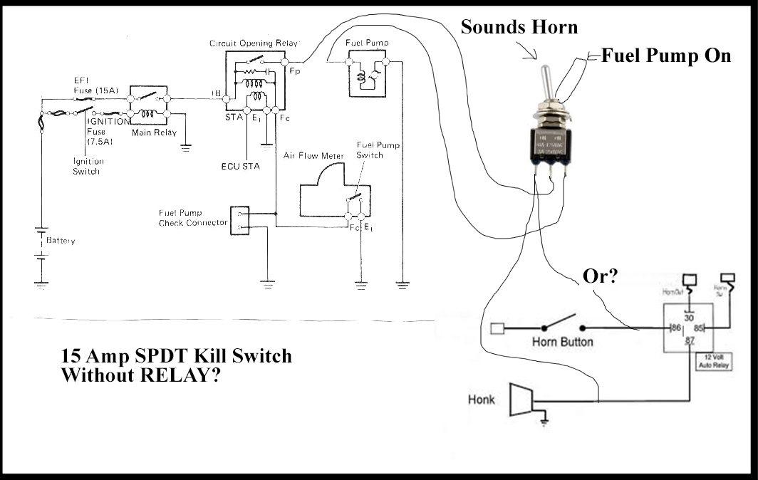
General Fuel Pump Kill Switch Wiring Diagram
This is a simplified representation of a typical installation. Always refer to your specific vehicle's wiring diagrams and the kill switch manufacturer's instructions.
Components Needed:
- SPST (Single Pole Single Throw) switch or equivalent
- Wire (same gauge as the fuel pump wire you’re tapping into)
- Wire connectors (crimp connectors, solder, etc.)
- Wire stripper/crimper
- Multimeter (for testing continuity)
- Electrical tape or heat shrink tubing
Steps:
- Locate the Fuel Pump Wire: Identify the power wire leading to the fuel pump. This can be done using a wiring diagram specific to your vehicle model and year. Alternatively, you can use a multimeter to test the wires at the fuel pump connector while the ignition is turned on (be careful and follow safety precautions). This wire is most commonly located near the fuel pump itself, or close to the fuel pump relay.
- Cut the Wire: Once you've identified the correct wire, carefully cut it in a location that's easily accessible for wiring but discreet enough to be concealed.
- Wire the Switch: Connect one end of the cut wire to one terminal on the SPST switch. Connect the other end of the cut wire to the other terminal on the switch.
- Secure the Connections: Use wire connectors or solder to ensure a secure and reliable connection. If soldering, use heat shrink tubing to insulate the connections. If using crimp connectors, make sure they are properly crimped and insulated.
- Hide the Switch: Conceal the switch in a hidden location within the vehicle. Common locations include under the dashboard, inside the glove compartment, or behind a panel.
- Test the Switch: Turn the ignition key to the "on" position (without starting the engine). With the switch in the "off" position, the fuel pump should not prime (you typically hear a buzzing sound). With the switch in the "on" position, the fuel pump should prime. Try starting the engine with the switch in both positions to confirm it's working as expected.
Important Considerations:
- Wire Gauge: Use wire that is the same gauge (thickness) as the fuel pump wire you are tapping into. Using a thinner wire can cause excessive voltage drop and overheating.
- Connection Quality: Poor connections are a common cause of kill switch failure. Ensure all connections are secure and properly insulated to prevent corrosion and short circuits.
- Switch Rating: Choose a switch that is rated for the current draw of the fuel pump. Consult your vehicle's service manual or the fuel pump specifications to determine the current draw.
Advanced Kill Switch Diagrams and Techniques
The simple SPST switch is a basic approach. More sophisticated installations can incorporate additional features and security measures.
Using a Relay as a Kill Switch
Instead of directly interrupting the fuel pump power wire with a switch, you can use a relay. This allows you to control the fuel pump circuit with a low-current signal from a hidden switch, making it more difficult for a thief to bypass the kill switch.
Diagram Overview:
- The hidden switch controls the relay coil.
- When the switch is "on," the relay coil is energized, and the relay contacts close.
- The closed relay contacts complete the fuel pump power circuit, allowing the fuel pump to operate.
- When the switch is "off," the relay coil is de-energized, the relay contacts open, and the fuel pump is disabled.
Benefits:
- Low-Current Control: The hidden switch only needs to handle a small current to control the relay coil, reducing the risk of overheating or switch failure.
- Increased Security: It's more difficult to bypass a relay-based kill switch because the thief would need to understand the relay circuit and its control mechanism.
Using a Normally Closed (NC) Relay
A normally closed (NC) relay adds another layer of security. In this setup, the fuel pump circuit is normally complete when the hidden switch is off. To start the car, you need to activate the hidden switch, energizing the relay coil and opening the relay contacts, which then allows the fuel pump to receive power.
The Logic: A thief searching for a simple open circuit (as in the SPST setup) would be fooled. They would need to actively close the circuit, which is counter-intuitive.
Timer-Based Kill Switches
These involve a timer circuit that momentarily enables the fuel pump. The driver has a few seconds after turning the ignition to activate the kill switch (e.g., by pressing a hidden button or combination of buttons). If the switch is not activated within the time limit, the fuel pump is disabled. This adds complexity, making it harder for thieves to start the car even if they find the wiring.
Wiring Diagram Considerations for Specific Vehicle Types
While the general principles remain the same, the specific wiring diagrams and wire colors will vary depending on the vehicle's make, model, and year. Here are some common considerations:
Older Vehicles (Pre-1990s)
Older vehicles typically have simpler wiring systems, making it easier to identify and access the fuel pump wire. However, the wiring may be more prone to corrosion and damage, so careful inspection is crucial. You may need to consult a physical repair manual for wiring diagrams as online resources might be limited.
Modern Vehicles (Post-2000s)
Modern vehicles have complex wiring harnesses and integrated electronic systems. It can be more challenging to identify the correct fuel pump wire and avoid interfering with other vehicle systems. Access to reliable wiring diagrams (e.g., from Mitchell OnDemand, Alldata) is essential. CAN (Controller Area Network) bus systems make it vital to avoid unintended consequences when modifying any electrical components.
Diesel Vehicles
Diesel vehicles have a different fuel system architecture than gasoline vehicles, often relying on high-pressure injection pumps. While the principle of interrupting the fuel supply remains the same, the specific wiring and components may differ. The kill switch may need to interrupt the power to the fuel shut-off solenoid or the electronic fuel control unit.
Troubleshooting Fuel Pump Kill Switch Problems
A malfunctioning kill switch can prevent the vehicle from starting or cause intermittent fuel delivery problems. Here are some common troubleshooting steps:
- Check Connections: Inspect all wiring connections for looseness, corrosion, or damage. Ensure the switch terminals are securely connected and the wire insulation is intact.
- Test the Switch: Use a multimeter to test the continuity of the switch in both the "on" and "off" positions. If the switch is faulty, replace it.
- Check the Relay (if applicable): If using a relay, test the relay coil and contacts. Ensure the relay is receiving power and is switching properly.
- Verify Voltage: Check the voltage at the fuel pump connector with the ignition on and the kill switch in the "on" position. The voltage should be close to the battery voltage.
- Bypass the Kill Switch: Temporarily bypass the kill switch by reconnecting the fuel pump wire directly. If the vehicle starts, the problem is likely with the kill switch or its wiring.
- Consult Wiring Diagrams: Refer to the vehicle's wiring diagrams to ensure the kill switch is wired correctly and is not interfering with other systems.
Disclaimer
Installing a fuel pump kill switch involves working with the vehicle's electrical system, which can be dangerous if not done correctly. Always disconnect the battery before working on the electrical system. If you are not comfortable working with electrical systems, seek professional assistance from a qualified mechanic or automotive electrician. Incorrect installation can damage the vehicle's electrical system and void warranties. The author and publisher are not responsible for any damages or injuries resulting from the use of this information.