How To Test Abs Sensor Using Multimeter
Experiencing issues with your car's ABS (Anti-lock Braking System)? A common culprit is a faulty ABS sensor. These sensors are crucial for monitoring wheel speed and preventing wheel lockup during braking. When they fail, your ABS light illuminates, and your braking performance can be compromised. Luckily, you can often diagnose a bad ABS sensor yourself using a multimeter. This article will guide you through the process.
Understanding ABS Sensors and Why They Fail
ABS sensors come in a couple of common types: inductive and Hall-effect sensors. Inductive sensors generate an AC voltage signal that varies with wheel speed. Hall-effect sensors, on the other hand, produce a digital (on/off) signal. Both types relay information to the ABS control module, which then adjusts braking pressure to individual wheels as needed.
Several factors can lead to ABS sensor failure. Common causes include:
- Physical damage: Road debris, impacts, or even corrosion can damage the sensor itself or its wiring.
- Contamination: Brake dust, dirt, and other contaminants can interfere with the sensor's ability to read wheel speed accurately.
- Wiring issues: Broken, frayed, or corroded wires can disrupt the signal between the sensor and the ABS control module.
- Internal failure: The sensor's internal components can simply wear out over time.
Recognizing the symptoms of a failing ABS sensor is the first step towards resolving the issue. Common symptoms include:
- ABS warning light illuminated on the dashboard.
- Traction control light illuminated (often linked to the ABS system).
- Reduced or absent ABS functionality during braking.
- Erratic braking or premature ABS activation.
Tools You'll Need
Before you start, gather the necessary tools:
- Multimeter: A digital multimeter (DMM) is essential for testing voltage, resistance, and continuity.
- Jack and Jack Stands: You'll need to safely lift the vehicle to access the sensors. Never work under a vehicle supported only by a jack.
- Wheel Chocks: Secure the wheels that remain on the ground.
- Wrench or Socket Set: For removing the wheel.
- Penetrating Oil (Optional): If the sensor is stuck, penetrating oil can help loosen it.
- Wiring Diagram (Recommended): A wiring diagram for your specific vehicle can be invaluable for identifying the correct sensor wires. You can usually find these online or in a repair manual.
- Gloves: To protect your hands.
Testing ABS Sensors with a Multimeter: Step-by-Step
Important Safety Note: Disconnect the negative battery terminal before starting any electrical work on your vehicle. This will help prevent accidental short circuits and potential injury.
Step 1: Identify the ABS Sensor
Locate the ABS sensor on the wheel hub you suspect is faulty. These sensors are typically mounted near the brake rotor or wheel bearing. They have a wire harness connected to them.
Step 2: Access the Sensor
Loosen the lug nuts on the wheel of the sensor you're testing. Then, using a jack, lift the vehicle and securely support it with jack stands. Remove the wheel to gain access to the sensor and its wiring. Chock the wheels remaining on the ground for extra safety.
Step 3: Visual Inspection
Carefully inspect the sensor, wiring, and connector for any signs of damage, such as cracks, breaks, corrosion, or loose connections. Clean the sensor head with a clean cloth to remove any debris that might be interfering with its operation. Address any obvious issues before proceeding with electrical testing.
Step 4: Testing Inductive ABS Sensors for Resistance
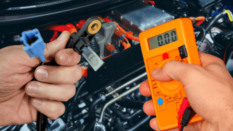
For inductive sensors, you can perform a resistance test. Disconnect the sensor's electrical connector. Set your multimeter to the ohms (Ω) setting. Touch the multimeter probes to the two terminals on the sensor itself (not the vehicle's wiring harness). A good inductive sensor will typically have a resistance value between 800 and 1200 ohms. Consult your vehicle's repair manual or online resources for the specific resistance range for your sensor. A reading of zero ohms (short circuit) or infinite ohms (open circuit) indicates a faulty sensor.
Step 5: Testing Hall-Effect ABS Sensors for Voltage
Testing Hall-effect sensors usually involves checking for a voltage signal. Since Hall-effect sensors are active sensors and require power to operate, do not disconnect the sensor connector. Back-probe the connector (carefully insert the multimeter probes into the back of the connector without damaging the wires) to access the sensor's signal wire and ground wire. Consult your vehicle's wiring diagram to identify the correct wires.
Set your multimeter to DC voltage. Turn the ignition key to the "on" position, but do not start the engine. Many Hall-effect sensors will have a reference voltage around 5V. With the wheel stationary, the sensor should output a steady voltage. Now, manually spin the wheel hub (have a helper do this, or carefully spin it yourself). The voltage reading should fluctuate as the wheel rotates, indicating the sensor is detecting the teeth on the tone ring (the toothed ring that the sensor reads). If the voltage remains constant or doesn't fluctuate, the sensor is likely faulty.
Step 6: Testing for AC Voltage (Optional, for Inductive Sensors)
Some advanced multimeters can measure AC voltage. This test provides another way to check inductive sensors. With the sensor connected, back-probe the signal wires. Set your multimeter to AC voltage. Start the engine. As the wheel rotates, the sensor should generate an AC voltage signal. The faster the wheel spins, the higher the AC voltage. The exact voltage will vary depending on the vehicle and sensor type, but the presence of a varying AC voltage signal indicates the sensor is likely functioning.
Step 7: Checking the Wiring Harness
Even if the sensor tests good, the problem might lie in the wiring harness. Use your multimeter to check for continuity between the sensor connector and the ABS control module connector. A lack of continuity indicates a broken or damaged wire. Also, check for shorts to ground by testing for continuity between each wire in the harness and the vehicle's chassis ground. There should be no continuity to ground. Repair or replace any damaged wiring.
Step 8: Reassembly and Testing
Once you've completed the testing, reconnect the sensor, reassemble the wheel, and lower the vehicle. Reconnect the negative battery terminal. Start the engine and drive the vehicle at a slow speed to see if the ABS light has turned off. You may need to drive a short distance for the ABS system to recalibrate. If the light remains on, you may need to use an OBD-II scanner with ABS capabilities to read the diagnostic trouble codes (DTCs) and pinpoint the exact problem.
What If the Sensor is Good?
If the ABS sensor tests good, the problem lies elsewhere in the ABS system. Other potential issues include:
- Faulty ABS control module.
- Problems with the hydraulic unit (ABS pump).
- Issues with the wheel speed sensor tone ring (damaged or dirty).
- Air in the brake lines.
These issues often require specialized diagnostic equipment and expertise. It's best to consult a qualified mechanic for further diagnosis and repair.
Approximate Repair Costs
Replacing an ABS sensor can range from $100 to $400, depending on the vehicle make and model and whether you choose to do the work yourself. The sensor itself typically costs between $30 and $150. Labor costs can vary from $70 to $250. If the problem lies in the wiring harness or ABS control module, the repair costs can be significantly higher. It's always a good idea to get a quote from a reputable mechanic before proceeding with any repairs.
Final Thoughts
Testing your ABS sensor with a multimeter is a valuable diagnostic step that can save you time and money. By following these steps, you can often identify a faulty sensor and determine whether it needs to be replaced. However, remember that the ABS system is a complex safety system. If you're not comfortable working on your vehicle's brakes, it's always best to seek professional help.