Mass Air Flow Sensor Diagram
The Mass Air Flow (MAF) sensor is a crucial component in modern internal combustion engines. It's the unsung hero responsible for accurately measuring the amount of air entering the engine, allowing the engine control unit (ECU) to deliver the correct fuel mixture. This precise air/fuel ratio is vital for optimal performance, fuel efficiency, and emissions control. But not all MAF sensors are created equal. From hot-wire anemometers to Karman vortex sensors, and even newer technologies finding their way into performance vehicles, the landscape of MAF sensor design is diverse and constantly evolving. Understanding these differences can be the key to diagnosing performance issues and even unlocking hidden potential in your ride.
MAF Sensor Fundamentals: A Quick Overview
At its core, a MAF sensor does one thing: measures the mass of air flowing into the engine. This information is then relayed to the ECU as an electrical signal, typically a voltage or frequency. The ECU uses this input, along with data from other sensors (like the oxygen sensor and throttle position sensor), to calculate the ideal amount of fuel to inject. A faulty MAF sensor can lead to a range of problems, including poor fuel economy, rough idling, hesitation during acceleration, and even a complete no-start condition.
While the basic principle remains the same, the technology used to measure airflow varies significantly. Here's a breakdown of some common types:
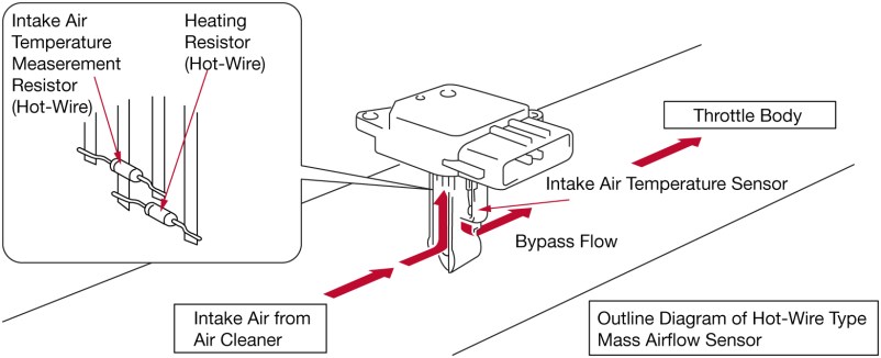
Hot-Wire Anemometer MAF Sensors
This is the most prevalent type, found in countless vehicles. A hot-wire MAF sensor uses a heated wire or film placed in the path of the incoming air. As air flows past the heated element, it cools down. The sensor measures the amount of electrical current required to maintain the element at a constant temperature. The higher the airflow, the more current is needed. This current value is then translated into an air mass reading by the ECU.
Pros:
- Relatively simple and inexpensive to manufacture.
- Quick response time.
- Good accuracy in most applications.
Cons:
- Susceptible to contamination from dirt, oil, and other debris. This contamination can insulate the hot-wire, leading to inaccurate readings.
- Can be damaged by improper cleaning.
- May require recalibration after cleaning (depending on the vehicle).
Real-world Driving Impression: Vehicles equipped with hot-wire MAF sensors generally offer smooth and predictable throttle response. However, performance can degrade noticeably if the sensor becomes dirty, leading to a sluggish feel and decreased fuel economy.
Hot-Film Anemometer MAF Sensors
Similar in principle to the hot-wire design, hot-film MAF sensors utilize a thin film instead of a wire. This film contains a miniature temperature sensor and a heater. The film is maintained at a constant temperature above the ambient air temperature. The ECU monitors the power required to keep the film at this temperature, correlating it to the mass airflow.
Pros:
- More robust and less prone to damage compared to hot-wire sensors.
- Potentially longer lifespan.
- May offer slightly improved accuracy.
Cons:
- Generally more expensive than hot-wire sensors.
- Still susceptible to contamination, though potentially less so.
- Response time may be slightly slower than hot-wire sensors in some applications.
Real-world Driving Impression: Hot-film MAF sensors tend to provide consistent performance over a longer period. They are often found in vehicles where reliability is paramount. The difference in driving feel compared to a hot-wire system is often subtle, but may be noticeable in high-performance applications.
Karman Vortex MAF Sensors
This technology relies on the principle of vortex shedding. A bluff body (a specially shaped obstruction) is placed in the path of the airflow. As air flows past the bluff body, it creates a series of swirling vortices. The frequency of these vortices is directly proportional to the airflow velocity. A sensor detects these vortices, and the ECU uses the frequency of the vortex shedding to calculate the air mass.
Pros:
- Less susceptible to contamination than hot-wire or hot-film sensors.
- Potentially more durable in harsh environments.
- Can measure a wider range of airflow velocities.
Cons:
- Can be more expensive than other types of MAF sensors.
- May have a slower response time compared to hot-wire sensors.
- The accuracy of the sensor can be affected by changes in air temperature and pressure.
Real-world Driving Impression: Karman vortex MAF sensors are often found in older vehicles and some diesel applications. The driving experience may be less refined compared to newer technologies, particularly in terms of throttle response. However, their robustness makes them well-suited for challenging operating conditions.
MAP Sensors and Speed-Density Systems: An Alternative Approach
While not strictly a MAF sensor, it's crucial to mention Manifold Absolute Pressure (MAP) sensors and speed-density systems. Instead of directly measuring airflow, these systems use a MAP sensor to measure the pressure inside the intake manifold. The ECU then uses this pressure reading, along with engine speed (RPM) and other parameters, to estimate the amount of air entering the engine. This approach is often used in turbocharged vehicles and some older engine designs.
Pros:
- Eliminates the need for a MAF sensor, reducing potential failure points.
- Can be more tolerant of modifications, such as aftermarket air intakes.
- Generally less expensive to implement.
Cons:
- Less accurate than direct airflow measurement, especially at higher engine speeds.
- Requires careful calibration to achieve optimal performance.
- Changes in atmospheric conditions can affect accuracy.
Real-world Driving Impression: Speed-density systems can provide good performance when properly tuned. However, they may not be as responsive or efficient as systems that use direct airflow measurement. Many modern performance vehicles are transitioning towards hybrid systems that combine MAP and MAF sensors for enhanced accuracy and adaptability.
MAF Sensor Diagram Variations: A Closer Look
The physical layout and wiring of a MAF sensor can vary depending on the vehicle make, model, and engine type. A typical MAF sensor diagram will show the following connections:
- Power Supply: Usually a 5V or 12V signal from the ECU.
- Ground: Provides a reference point for the electrical circuit.
- Signal Wire: Transmits the airflow reading to the ECU. This can be an analog voltage signal or a digital frequency signal.
- Intake Air Temperature (IAT) Sensor: Many MAF sensors integrate an IAT sensor to measure the temperature of the incoming air. This information is used to compensate for changes in air density.
Here's a simplified spec table highlighting the differences:
| Sensor Type | Typical Voltage Range | Frequency Output | Integrated IAT Sensor |
|---|---|---|---|
| Hot-Wire MAF | 0-5V | No | Yes (often) |
| Hot-Film MAF | 0-5V | No | Yes (often) |
| Karman Vortex MAF | N/A | Yes | No (typically separate) |
Important Note: Always consult the vehicle's service manual for the correct MAF sensor diagram and testing procedures. Incorrect wiring can damage the sensor or the ECU.
Upgrading and Tuning: Unleashing Hidden Power
For enthusiasts looking to boost their vehicle's performance, upgrading the MAF sensor can be a viable option. A larger diameter MAF sensor can measure a greater volume of airflow, allowing for increased horsepower. However, it's crucial to ensure that the ECU is properly calibrated to account for the new sensor. This often requires custom tuning or the use of a piggyback ECU.
Furthermore, cleaning the MAF sensor is a routine maintenance task that can significantly improve performance. Use a dedicated MAF sensor cleaner and avoid touching the delicate sensing element. Always disconnect the battery before cleaning to prevent accidental damage.
Warning: Incorrectly tuning the ECU or using an incompatible MAF sensor can lead to engine damage. Always consult with a qualified tuner before making any modifications.
Conclusion: The Silent Guardian of Your Engine
The MAF sensor plays a vital role in ensuring optimal engine performance and efficiency. Understanding the different types of MAF sensors and their characteristics can help you diagnose problems, maintain your vehicle, and even unlock hidden power. From the ubiquitous hot-wire sensor to the more robust Karman vortex design, the world of MAF sensor technology is constantly evolving. Keep an eye on future developments, as new and improved sensors are sure to emerge, pushing the boundaries of engine performance even further.
So, here's the fun part: Which MAF sensor technology do you think is the most reliable in extreme conditions, say a Baja race? Is old-school Karman Vortex tech the answer, or are there modern coatings that make hot-film sensors impervious to dust and debris? Let the debate begin!