My Speed Gauge Is Not Working
Alright, so your speedometer isn't playing ball. That's a common headache, but thankfully, often fixable in your own garage. Let's dive into the likely culprits and how to diagnose them. We'll assume you've already checked the super obvious stuff like the fuse – but if not, start there! It's usually labeled "Instrument Cluster" or "Speedometer" in your fuse box diagram.
Understanding the Basics: How Speedometers Work
Before we get our hands dirty, let's quickly review how speedometers generally function. There are two main types: mechanical and electronic. Modern cars almost exclusively use electronic speedometers, but understanding the older, mechanical type can sometimes provide useful context.
Mechanical Speedometers: A Relic of the Past (Mostly)
In a mechanical system, a cable directly connects to the transmission. As the transmission's output shaft rotates (driven by your wheels turning), so does this cable. The cable then spins a magnet inside the speedometer housing. This rotating magnet creates a magnetic field that pulls on a metal cup attached to the speedometer needle. The faster you go, the faster the magnet spins, the stronger the magnetic pull, and the further the needle deflects, showing your speed.
These systems are simple but prone to mechanical failure, particularly cable breakage or binding. A squealing or erratic speedometer reading is a classic sign of a failing cable.
Electronic Speedometers: The Modern Standard
Electronic speedometers rely on sensors to detect wheel speed and transmit that information to the car's ECU (Electronic Control Unit). The ECU then processes this data and sends a signal to the instrument cluster, which displays the speed on your speedometer.
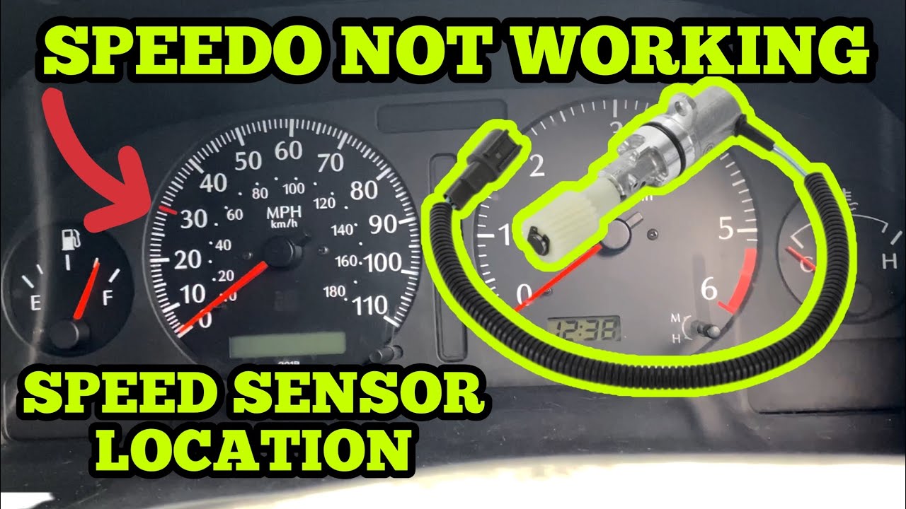
The key component here is the vehicle speed sensor (VSS). This sensor is usually mounted on the transmission or a wheel hub. The VSS generates a signal – either an analog voltage or a digital pulse – that's proportional to the speed of the rotating component. Newer cars might also use wheel speed sensors which are part of the ABS/Traction Control system to obtain vehicle speed information.
Troubleshooting Steps: Pinpointing the Problem
Now, let’s get into diagnosing your faulty speedometer. We'll focus on electronic speedometers since those are the most common these days. Here’s a systematic approach:
- Check for Error Codes: This is always step one. Use an OBD-II scanner to check for any stored Diagnostic Trouble Codes (DTCs). Codes related to the VSS, ABS, or transmission are red flags. Common codes include P0500 (Vehicle Speed Sensor A Malfunction), P0501 (Vehicle Speed Sensor A Range/Performance), and codes related to individual wheel speed sensors (e.g., Cxxxx codes). Write down any codes you find, as they provide crucial clues.
- Inspect the Vehicle Speed Sensor (VSS): Locate the VSS on your transmission. Consult your vehicle's repair manual or online resources to find its exact location. Carefully inspect the sensor's wiring harness for any signs of damage, corrosion, or loose connections. Unplug the connector and check for corrosion inside the connector itself. Clean the connector pins with electrical contact cleaner and re-plug it firmly.
- Test the VSS: This is where a multimeter comes in handy. With the VSS unplugged, use the multimeter to check for power and ground at the connector. Consult your repair manual for the specific pinout diagram and expected voltage values. If power and ground are present, the problem is likely with the sensor itself.
- Testing the VSS signal: Depending on the VSS type (analog or digital), the testing procedure varies.
- Analog VSS: Set your multimeter to measure AC voltage. Connect the multimeter leads to the signal wire and ground. Have someone slowly rotate one of the wheels (or preferably, use a jack to lift the drive wheels if safe to do so). You should see a fluctuating AC voltage reading that increases as the wheel speed increases. If the voltage remains constant or is zero, the sensor is likely faulty.
- Digital VSS: Set your multimeter to measure DC voltage and frequency (Hz). Connect the multimeter leads to the signal wire and ground. As the wheel rotates, you should see a pulsed DC voltage reading and a frequency reading that increases with wheel speed. Some multimeters have a "duty cycle" function, which can also be used to test digital signals. Again, a constant or zero reading suggests a faulty sensor. A much better way to test a digital VSS is using a oscilloscope, this allows you to see the signal and any irregular behaviour.
- Check the Wiring Harness: If the VSS appears to be functioning correctly, the problem might lie in the wiring harness between the sensor and the ECU or instrument cluster. Use a multimeter to perform a continuity test on the signal wire. Disconnect the VSS and the ECU (or instrument cluster) and measure the resistance between the corresponding pins. You should see close to zero ohms, indicating a continuous wire. A high resistance or an open circuit indicates a break in the wire. Repair any damaged wiring or replace the harness if necessary. Finding breaks in the wiring can be tricky, as they often occur inside the insulation, so a thorough visual inspection and wiggling of the wires while testing continuity is essential.
- Inspect the Instrument Cluster: While less common, the instrument cluster itself can be the culprit. If you've ruled out the VSS, wiring, and ECU, consider the possibility of a faulty speedometer gauge or the cluster's internal circuitry. Some instrument clusters are known to have soldering issues that can cause intermittent or complete speedometer failure. A visual inspection of the circuit board for cracked solder joints or burnt components is worthwhile. Note: Working on instrument clusters requires a delicate touch and a good understanding of electronics. If you're not comfortable with this level of repair, it's best to consult a professional.
- ECU Issues: In rare cases, the ECU itself might be the source of the problem. If the ECU isn't correctly processing or transmitting the VSS signal, the speedometer won't work. ECU diagnosis and repair are usually best left to specialized technicians with access to advanced diagnostic equipment and programming tools. However, if you suspect an ECU issue, make sure the ECU is properly grounded and receiving the correct power supply.
- ABS System Interference: Some vehicles rely on the ABS system's wheel speed sensors to provide speed information to the ECU. If there are problems with the ABS system (e.g., a faulty ABS sensor or module), it could indirectly affect the speedometer. Check for ABS-related error codes and address any ABS issues before further diagnosing the speedometer.
Tools You'll Need
To tackle this project, you'll likely need the following tools:
- OBD-II Scanner: Essential for reading error codes.
- Multimeter: For testing voltage, continuity, and resistance.
- Socket Set and Wrenches: For removing and installing the VSS.
- Electrical Contact Cleaner: For cleaning connectors.
- Wiring Diagram: Crucial for identifying the correct wires and pins. Your vehicle's repair manual is your best source.
- Jack and Jack Stands: For safely lifting the vehicle.
- Wire Strippers, Crimpers, and Soldering Iron (Optional): For repairing damaged wiring.
- Test Light (Optional): A simple tool for quickly checking for power.
Specific Scenarios and Considerations
- Aftermarket Modifications: If you've recently installed any aftermarket modifications, such as larger tires or a different gear ratio, the speedometer might be inaccurate or not working at all. These modifications can affect the VSS signal and require recalibration of the speedometer. Aftermarket speedo correction modules are available to address this issue.
- Transmission Work: If you've recently had your transmission rebuilt or replaced, the VSS might not be properly installed or connected. Double-check the installation and wiring of the VSS.
- Intermittent Problems: Intermittent speedometer problems can be particularly frustrating to diagnose. The issue might only occur under certain conditions (e.g., when the engine is hot or when the vehicle is under load). In these cases, it's helpful to use a data logger to record the VSS signal over time and identify any patterns or anomalies.
- Check Engine Light (CEL): A faulty speedometer can sometimes trigger the Check Engine Light. Address the speedometer issue first, as it might be the root cause of the CEL. After repairing the speedometer, clear the error codes and see if the CEL returns.
When to Call a Professional
While many speedometer problems can be resolved with DIY troubleshooting, there are times when it's best to seek professional help:
- If you're not comfortable working with electrical systems.
- If you're unable to diagnose the problem after following the troubleshooting steps outlined above.
- If you suspect an ECU issue.
- If the problem is intermittent and difficult to replicate.
A qualified mechanic has access to specialized diagnostic equipment and expertise to quickly and accurately pinpoint the problem and perform the necessary repairs.
By systematically working through these steps, you should be able to diagnose and repair your faulty speedometer. Remember to always prioritize safety and consult your vehicle's repair manual for specific instructions and wiring diagrams. Good luck!