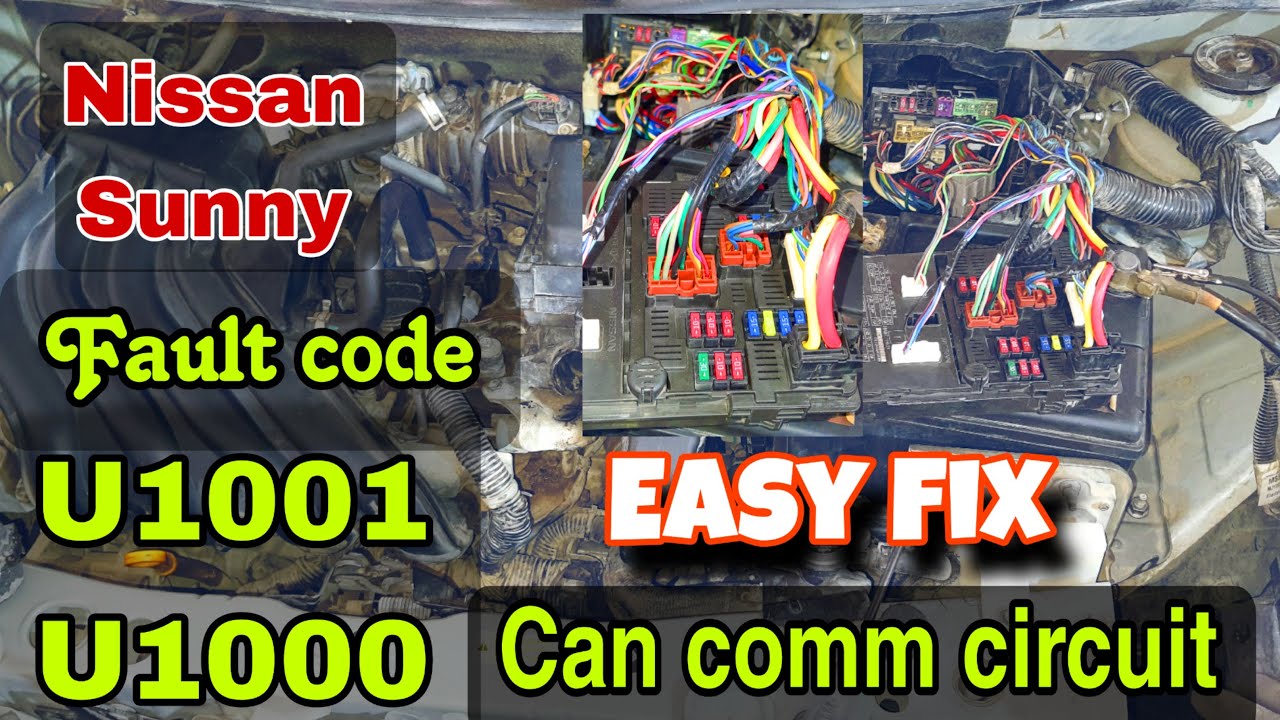
Nissan U1000 Can Comm Circuit
Alright, let's dive into the Nissan U1000 CAN communication circuit. This isn't your average "check engine light is on" kind of problem. U1000 indicates a deeper issue within the vehicle's communication network. Understanding this system is crucial for diagnosing a wide range of problems, from seemingly unrelated sensor failures to complete engine immobilisation.
What is CAN and Why is it Important?
CAN stands for Controller Area Network. Think of it as the vehicle's central nervous system. In older cars, each sensor and control module (like the ECU, ABS, and transmission control unit) had its own dedicated wiring harness running back to the central computer. This meant a lot of wires, making the car heavy, complex, and prone to wiring failures. Modern cars are vastly more sophisticated. A CAN bus allows these modules to communicate with each other using a shared, two-wire system.
These two wires are typically labeled CAN High (CANH) and CAN Low (CANL). The modules "talk" to each other by sending digital messages along these wires. Each message contains information about the sensor's data or the controller's command, as well as the ID of the sender and receiver. For example, the ABS module might send a message indicating wheel speed to the ECU, so the ECU can adjust the fuel injection or ignition timing.
Key Concept: CAN bus reduces wiring complexity, allows for advanced vehicle functions, and facilitates diagnostics.
How does CAN Communication Work?
CAN communication relies on differential signaling. This means that data is transmitted by the *difference* in voltage between the CANH and CANL wires, not the absolute voltage of each wire. This makes the system very resistant to electrical noise and interference. When a module sends a 'dominant' bit (logically a '0'), CANH is pulled high (typically around 3.5V) and CANL is pulled low (typically around 1.5V). When a module sends a 'recessive' bit (logically a '1'), both CANH and CANL are pulled towards a common voltage, usually around 2.5V. The receiving modules then detect the voltage difference and decode the message.
To visualize this, imagine looking at the CANH and CANL signals on an oscilloscope. You would see a series of voltage pulses representing the binary data being transmitted.
Nissan U1000: Diagnosis
The U1000 code, specific to Nissan (and sometimes Infiniti) vehicles, generally indicates a CAN communication circuit malfunction. It doesn't tell you exactly *where* the problem is, only that one or more modules are unable to communicate correctly on the CAN bus.
Possible Causes of U1000:
- Faulty Control Module: One of the modules connected to the CAN bus may be malfunctioning and disrupting communication. This is the most common culprit.
- Wiring Issues: Damaged, corroded, or shorted wiring in the CAN bus circuit. This includes the CANH and CANL wires, as well as the ground and power wires supplying the modules.
- CAN Bus Termination Resistors: The CAN bus requires termination resistors at each end of the network (typically 120 ohms). If a resistor is missing or faulty, it can cause communication errors.
- Loose Connectors: Poor connections at any point in the CAN bus circuit can interrupt communication.
- Software Glitches: In rare cases, a software glitch in one of the modules can cause communication problems.
- Power Supply Issues: Insufficient or fluctuating power supply to any of the modules can disrupt CAN communication.
Diagnostic Steps:
- Gather Information: Use a scan tool to retrieve all diagnostic trouble codes (DTCs) from all modules on the vehicle. This will give you a broader picture of the problem. Note down *all* DTCs, not just the U1000. Also, see if you can read live data parameters from various modules. If you can't communicate with certain modules at all, this points to a more localized issue near that specific module.
- Visual Inspection: Carefully inspect the CAN bus wiring harness for any signs of damage, corrosion, or chafing. Pay close attention to areas where the harness passes near sharp edges or hot components. Check all connectors for corrosion or loose pins. Look for aftermarket accessories that may have been poorly wired into the CAN bus.
- Check CAN Bus Termination Resistors: Locate the termination resistors (typically within the ECU and the IPDM – Intelligent Power Distribution Module) and measure their resistance using a multimeter. You should find each resistor around 120 ohms. With the vehicle off and the battery disconnected, you can measure the resistance across the CANH and CANL wires at the DLC (Data Link Connector, the OBD2 port). You should see approximately 60 ohms (because the two 120-ohm resistors are in parallel). If you measure significantly higher or lower resistance, it indicates a problem with one of the termination resistors or a short in the CAN bus wiring.
- Voltage Checks: With the ignition on (but engine off), use a multimeter to measure the voltage on the CANH and CANL wires at the DLC. You should typically see CANH around 2.5-3.5V and CANL around 1.5-2.5V. If either voltage is significantly outside of this range, it indicates a problem.
- Oscilloscope Testing: An oscilloscope is the best tool for diagnosing CAN bus problems. Connect the oscilloscope to the CANH and CANL wires at the DLC and observe the waveform. You should see a clear, well-defined signal with consistent voltage levels. Look for signs of signal distortion, noise, or missing bits. If you see a flat line on either CANH or CANL, it suggests a short to ground or open circuit.
- Module Isolation: If you suspect a faulty module, you can try isolating it from the CAN bus. Disconnect the module's CANH and CANL wires and see if the U1000 code clears. If it does, the disconnected module is likely the culprit. Important: Be sure to disconnect the battery before disconnecting any modules. Consult the service manual for your specific vehicle to locate the CAN bus wiring and module locations.
- Wiring Continuity Tests: Use a multimeter to check the continuity of the CANH and CANL wires between modules. Disconnect the battery and any modules you're testing from the circuit before doing so to prevent damage. Look for open circuits or shorts to ground.
Important Considerations:
- Consult a Service Manual: Always refer to the factory service manual for your specific Nissan model. The manual contains detailed information about the CAN bus wiring diagram, module locations, and diagnostic procedures.
- Battery Condition: Ensure the battery is fully charged before performing any diagnostic tests. A weak battery can cause erratic CAN bus behavior.
- Aftermarket Accessories: Poorly installed aftermarket accessories (like alarms, stereos, or remote starters) can interfere with CAN bus communication. Disconnect any aftermarket accessories before starting your diagnosis.
- Professional Help: If you're not comfortable performing these diagnostic steps, it's best to take your vehicle to a qualified mechanic with experience diagnosing CAN bus problems. Misdiagnosis or improper repairs can damage the vehicle's electrical system.
Addressing a U1000 code can be challenging, but with patience, a systematic approach, and the right tools, you can often track down the problem and restore your Nissan's communication network. Remember to always prioritize safety and consult the service manual for accurate information.