Symptoms Of Bad Tail Light Circuit Board
The tail light circuit board, often an unsung hero in automotive lighting systems, plays a crucial role in ensuring vehicle safety and regulatory compliance. When this board malfunctions, it can lead to a cascade of problems, impacting visibility and potentially resulting in accidents. For automotive professionals, a comprehensive understanding of the symptoms, underlying causes, and best practices for diagnosis and repair is essential.
Symptoms of a Failing Tail Light Circuit Board
Identifying a failing tail light circuit board often relies on recognizing specific and sometimes intermittent symptoms. These can manifest in several ways:
- Dim or Non-Functional Lights: This is perhaps the most obvious sign. Individual bulbs or the entire tail light assembly may exhibit reduced brightness or complete failure. The circuit board may not be providing adequate voltage or current to the bulbs.
- Flickering Lights: Intermittent connections or component failures on the board can cause the tail lights to flicker erratically. This is often a sign of a loose connection or a failing capacitor.
- Incorrect Bulb Illumination: The circuit board controls the activation of different bulbs for various functions (brake lights, turn signals, running lights). A malfunctioning board can lead to the wrong bulbs illuminating, or combinations of bulbs lighting up incorrectly. For example, the brake light might illuminate when the turn signal is activated.
- "Ghosting" or Residual Illumination: Even when the car is off and the lights are supposedly deactivated, a failing circuit board might allow a small amount of current to leak through, causing a faint glow in the tail lights.
- Error Codes: Modern vehicles equipped with advanced diagnostic systems may display error codes related to the tail light circuit. These codes can be read using an OBD-II scanner and provide valuable information about the specific fault. Examples might include codes related to open circuits, short circuits, or low voltage conditions in the tail light circuit.
- Overheating: While less common, a severely damaged circuit board can overheat, potentially damaging surrounding components or even posing a fire risk. This is usually accompanied by a burning smell.
Technical Causes and Engineering Choices
The tail light circuit board is a relatively simple, yet crucial electronic assembly. It typically comprises:
- PCB (Printed Circuit Board): The foundation of the board, providing conductive pathways for electrical signals. PCB material is usually FR-4, a fiberglass epoxy laminate chosen for its electrical insulation properties and flame retardancy. The thickness and copper tracing weight are important for handling current loads.
- Resistors: Used to limit current flow and provide voltage drops to the various bulbs. Common resistor types include carbon film and metal film resistors, chosen for their tolerance and power rating.
- Capacitors: Used for filtering and smoothing voltage, as well as for timing functions. Electrolytic capacitors are common, but their lifespan can be affected by heat.
- Diodes: Used to allow current flow in only one direction, protecting sensitive components from reverse voltage. Schottky diodes are often used for their fast switching speeds.
- Transistors: Used as electronic switches to control the activation of the bulbs. Bipolar junction transistors (BJTs) and MOSFETs are both used, with MOSFETs becoming more common due to their lower on-resistance.
- Connectors: Provide a connection point for the wiring harness that supplies power and control signals to the board. The quality and design of these connectors are critical to prevent corrosion and ensure reliable electrical contact.
Engineering choices in the design of the tail light circuit board aim to balance cost, performance, and reliability. Factors considered include:
- Component Selection: Choosing components with appropriate voltage and current ratings is crucial for preventing premature failure. Automotive-grade components are designed to withstand the harsh environmental conditions found in vehicles (temperature extremes, vibration, humidity).
- Trace Width and Spacing: The width of the copper traces on the PCB must be sufficient to handle the expected current load. Insufficient trace width can lead to overheating and voltage drop. Spacing between traces must be adequate to prevent short circuits.
- Thermal Management: Heat generated by the components can significantly reduce their lifespan. Proper thermal management techniques, such as using heat sinks or thermally conductive materials, are essential for ensuring long-term reliability.
- Environmental Protection: The circuit board must be protected from moisture, dust, and other contaminants. Conformal coatings are often applied to the board to provide this protection.
Comparison with Alternatives: LED Tail Lights
Traditional incandescent bulbs, which are common failure point within older tail light assemblies, are being increasingly replaced by LED (Light Emitting Diode) tail lights. LED tail lights offer several advantages:
LED Tail Lights - Pros:
- Longer Lifespan: LEDs have a significantly longer lifespan than incandescent bulbs, reducing the need for frequent replacements.
- Lower Power Consumption: LEDs consume less power than incandescent bulbs, reducing the load on the vehicle's electrical system.
- Faster Response Time: LEDs illuminate almost instantly, providing a quicker warning to other drivers.
- Brighter Illumination: LEDs can produce a brighter and more focused light output, improving visibility.
- Design Flexibility: LEDs can be easily integrated into complex and aesthetically pleasing tail light designs.
LED Tail Lights - Cons:
- Higher Initial Cost: LED tail light assemblies are typically more expensive than incandescent assemblies.
- Complexity: LED tail light systems are more complex and usually have dedicated control module that may also fail.
- Heat Sensitivity: While LEDs themselves are energy-efficient, they can be sensitive to heat. Poor thermal management can reduce their lifespan.
- Repairability: Repairing LED tail light assemblies can be more challenging than repairing incandescent assemblies. Individual LEDs may not be replaceable, requiring replacement of the entire assembly.
While LED tail lights offer significant advantages in terms of lifespan and performance, they also introduce new challenges in terms of cost, complexity, and repairability. Notably, LED tail light assemblies still often rely on circuit boards for control and power distribution, meaning that the underlying failure mechanisms (corrosion, component failure due to heat and vibration) are still relevant.
Reliability Aspects and Common Failure Points
The reliability of tail light circuit boards is affected by several factors:
- Environmental Conditions: Exposure to extreme temperatures, vibration, and moisture can accelerate the degradation of components.
- Component Quality: The quality of the components used in the circuit board is a critical factor in determining its lifespan. Using automotive-grade components is essential for ensuring reliability in harsh environments.
- Manufacturing Quality: Poor soldering, improper component placement, or contamination during manufacturing can lead to premature failure.
- Overvoltage and Overcurrent: Voltage spikes or excessive current can damage sensitive components. Proper circuit protection measures, such as fuses and surge suppressors, are essential for preventing these types of failures.
Common failure points on tail light circuit boards include:
- Corrosion: Moisture and road salt can corrode the copper traces and component leads, leading to open circuits and intermittent connections.
- Component Failure: Resistors, capacitors, and transistors can fail due to overheating, overvoltage, or age. Electrolytic capacitors are particularly prone to failure due to drying out.
- Connector Issues: The connectors that connect the circuit board to the wiring harness can become corroded or loose, leading to poor electrical contact.
- Solder Joint Cracks: Vibration and thermal cycling can cause solder joints to crack, leading to intermittent connections.
Maintenance Tips and Diagnostic Procedures
Preventive maintenance can help extend the lifespan of tail light circuit boards. Regular inspection for signs of corrosion, loose connections, or physical damage is essential. Cleaning the connectors and applying dielectric grease can help prevent corrosion. If a tail light circuit board is suspected of being faulty, the following diagnostic procedures can be used:
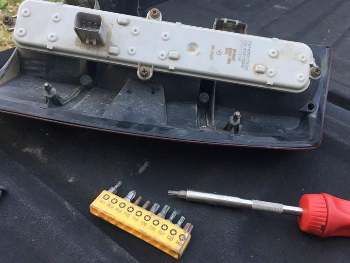
- Visual Inspection: Carefully inspect the circuit board for signs of corrosion, damaged components, or cracked solder joints.
- Voltage and Continuity Testing: Use a multimeter to check the voltage and continuity of the various circuits on the board. Compare the readings to the vehicle's wiring diagram to identify any discrepancies.
- Component Testing: Use a component tester to check the functionality of individual components, such as resistors, capacitors, and transistors.
- Oscilloscope Analysis: An oscilloscope can be used to analyze the waveforms of the signals on the board, providing valuable information about the circuit's operation.
- Thermal Imaging: A thermal imaging camera can be used to identify hotspots on the circuit board, indicating areas of excessive heat generation.
If a tail light circuit board is found to be faulty, it may be possible to repair it by replacing the damaged components. However, in some cases, it may be more cost-effective to replace the entire circuit board. Replacing the entire tail light assembly might be necessary, especially in cases involving significant physical damage or with tightly integrated LED systems.
Future Trends in Automotive Lighting
The automotive lighting industry is rapidly evolving. Some of the key trends include:
- Increased Use of LEDs: LEDs are becoming increasingly common in all types of automotive lighting applications, including tail lights, headlights, and interior lighting.
- Advanced Driver-Assistance Systems (ADAS): ADAS features, such as adaptive headlights and automatic high beams, are becoming more prevalent. These systems rely on sophisticated sensors and control algorithms to adjust the lighting based on driving conditions.
- OLED (Organic Light Emitting Diode) Technology: OLEDs offer several advantages over LEDs, including thinner profile, greater flexibility, and wider viewing angle. OLEDs are being used in tail lights to create unique and visually appealing designs.
- Connectivity: Future automotive lighting systems may be connected to the cloud, allowing for remote diagnostics, software updates, and personalized lighting settings.
- Integrated Sensors: Tail light assemblies may incorporate sensors for detecting objects in the vehicle's blind spots or for monitoring the condition of the road surface.
Conclusion
The tail light circuit board, while seemingly simple, is a vital component in modern vehicles. Understanding its function, failure modes, and diagnostic procedures is crucial for automotive professionals. As automotive technology continues to advance, the complexity of lighting systems will increase, requiring technicians to stay up-to-date with the latest trends and technologies. The move towards more sophisticated LED and OLED systems, coupled with increasing integration with ADAS, necessitates a continued focus on diagnostics and repair techniques specific to these advanced systems. The automotive industry is on a path towards greater integration and automation, and lighting systems are no exception, demanding ongoing professional development for automotive technicians.