2001 Nissan Frontier Manual Transmission
The 2001 Nissan Frontier, a workhorse pickup truck, offered a robust and relatively straightforward manual transmission. While automatics have gained prominence, the manual gearbox remains a compelling option for enthusiasts and those seeking greater control and fuel efficiency. This article delves into the inner workings of the 2001 Frontier's manual transmission, dissecting its components and explaining how they interact to deliver power to the wheels.
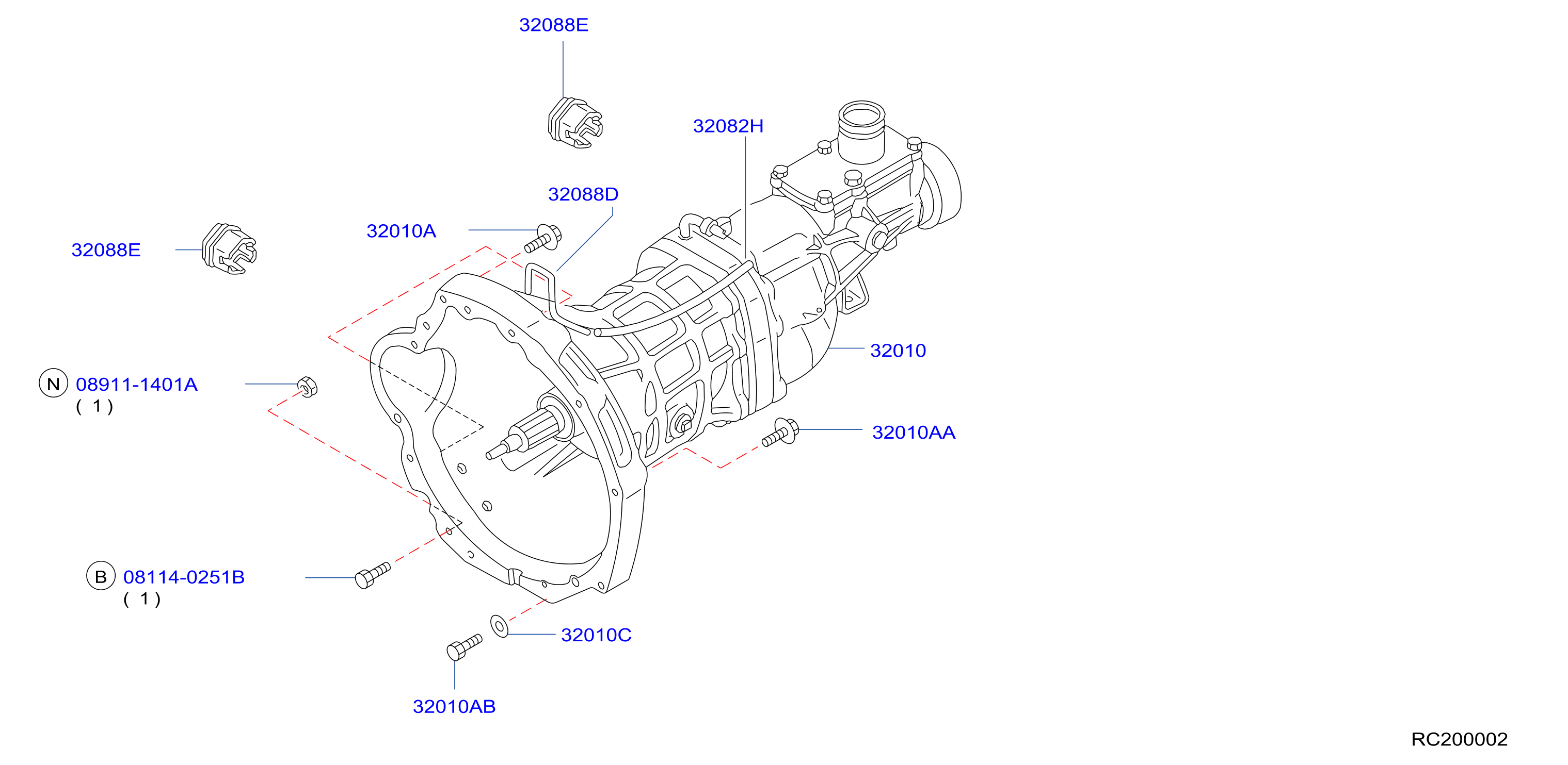
Overview of the Transmission
The specific manual transmission found in the 2001 Frontier varied slightly depending on the engine and drivetrain configuration. However, the fundamental principles of operation remained consistent. It's typically a 5-speed transmission (with the possibility of a 4-speed in some very base models, though less common). This implies five forward gears and one reverse gear. The transmission's primary function is to multiply engine torque and transmit it to the driveshaft, which in turn powers the rear axle (or both axles in a 4x4 model).
Essentially, a manual transmission is a gear reduction system. Different gear ratios provide varying levels of torque multiplication. Lower gears (1st and 2nd) offer high torque for acceleration and climbing hills, while higher gears (4th and 5th) provide lower torque but higher speeds for efficient cruising.
Key Components and Their Function
Input Shaft and Clutch
The input shaft is the transmission's gateway to the engine. It connects directly to the engine's flywheel via the clutch. The clutch's function is to disconnect the engine from the transmission, allowing the driver to shift gears without damaging the transmission. When the clutch pedal is depressed, the clutch disc is disengaged from the flywheel, interrupting the power flow. Releasing the pedal engages the clutch, transferring power to the input shaft. The input shaft then spins at the same speed as the engine when the clutch is engaged.
The clutch system consists of several parts: the flywheel (attached to the engine crankshaft), the clutch disc (a friction plate splined to the input shaft), the pressure plate (which presses the clutch disc against the flywheel), and the release bearing (which moves the pressure plate to disengage the clutch). The release bearing is activated by the clutch fork, which is connected to the clutch pedal linkage.
Gears and Shafts
Inside the transmission casing, you'll find a complex arrangement of gears mounted on several shafts. The most important shafts are the input shaft (already discussed), the main shaft (also called the output shaft), and the countershaft (also called the layshaft). The input shaft carries the engine's power into the transmission. The countershaft is driven by a gear on the input shaft and, in turn, drives the gears on the main shaft. The main shaft is connected to the driveshaft and transmits power to the wheels.
Each gear on the main shaft has a corresponding gear on the countershaft. These gear pairs have different sizes and numbers of teeth, resulting in different gear ratios. When a specific gear is selected, that gear on the main shaft is locked to the shaft, allowing it to transmit power. The other gears on the main shaft are free to spin, but they don't transmit power because they are not locked.
Synchronizers
Synchronizers are crucial components that ensure smooth gear changes. Without synchronizers, shifting gears would be a noisy and potentially damaging affair. Synchronizers work by matching the speed of the gear being selected to the speed of the main shaft before the gear is fully engaged. This is achieved through friction. A synchronizer ring, made of a friction material, is pressed against a cone-shaped surface on the gear. This friction causes the gear and the main shaft to spin at the same speed, allowing the shift sleeve to slide into place smoothly.
Synchronizers are typically comprised of several components: the synchronizer ring, the synchronizer sleeve, the hub, and the blocking ring. The blocking ring prevents the shift sleeve from engaging the gear until the speeds are synchronized. This protects the gear teeth from damage and reduces noise.
Shift Mechanism
The shift mechanism translates the driver's movement of the gearshift lever into the appropriate gear selection within the transmission. The shift lever is connected to a series of rods and forks that move the synchronizer sleeves. Each shift fork is responsible for engaging a specific gear or pair of gears (for example, 1st and 2nd gear might share a shift fork). The shift forks slide along rails inside the transmission housing.
A detent mechanism is used to hold the shift forks in the selected gear position. This prevents the transmission from popping out of gear accidentally. Detents typically consist of a spring-loaded ball that fits into notches on the shift rails.
Operation of the Transmission
To understand how the transmission works as a whole, let's walk through the process of shifting gears:
- The driver depresses the clutch pedal, disengaging the engine from the transmission.
- The driver moves the gearshift lever to the desired gear position.
- This movement actuates the shift linkage, which moves the appropriate shift fork.
- The shift fork moves the synchronizer sleeve towards the selected gear.
- The synchronizer ring contacts the cone-shaped surface on the gear, synchronizing the gear's speed with the main shaft's speed.
- Once the speeds are synchronized, the blocking ring allows the shift sleeve to slide fully into engagement with the gear.
- The selected gear is now locked to the main shaft, transmitting power to the driveshaft.
- The driver releases the clutch pedal, re-engaging the engine with the transmission.
Each gear selection involves a similar process, but with different gear ratios being engaged. The neutral position is achieved when no gear is engaged, allowing the main shaft to spin freely without transmitting power.
Reverse Gear
Reverse gear typically employs an idler gear. This gear sits between the countershaft and the main shaft, reversing the direction of rotation of the main shaft. Because the idler gear is an additional gear in the power path, reverse gear often has a different gear ratio than the forward gears. This can sometimes result in a noticeable "whine" when driving in reverse.
Lubrication
Proper lubrication is essential for the longevity and smooth operation of the manual transmission. Transmission fluid lubricates the gears, bearings, and synchronizers, reducing friction and wear. The correct type and amount of transmission fluid are critical. Consult the 2001 Nissan Frontier's owner's manual for specific recommendations. Changing the transmission fluid at the recommended intervals is crucial for maintaining optimal performance.
Common Issues and Maintenance
Manual transmissions are generally robust, but they are not immune to problems. Common issues include:
- Worn synchronizers: This can lead to difficulty shifting gears, especially into certain gears. Grinding noises during shifting are a telltale sign of worn synchronizers.
- Clutch problems: A worn clutch disc can cause slipping, making it difficult to accelerate. A faulty pressure plate or release bearing can also cause clutch problems.
- Bearing failure: Worn or damaged bearings can cause noise and vibration.
- Fluid leaks: Leaks can lead to low fluid levels, which can damage the transmission.
Regular maintenance, including fluid changes and inspections, can help prevent these problems. Paying attention to unusual noises or shifting difficulties can also help catch problems early, before they become more serious.
Understanding the mechanics of your 2001 Nissan Frontier's manual transmission empowers you to diagnose potential issues and appreciate the intricate engineering that delivers power to the wheels. While modern vehicles increasingly favor automatic transmissions, the manual gearbox continues to offer a direct connection to the driving experience for those who value control and engagement.