2006 Nissan Altima Ignition Coil Diagram
The 2006 Nissan Altima, a popular mid-size sedan, relies on a carefully orchestrated ignition system to bring its engine to life. At the heart of this system lies the ignition coil, a component responsible for transforming the relatively low voltage from the car's battery into the high voltage necessary to create a spark at the spark plugs, thus igniting the air-fuel mixture in the engine cylinders. Understanding the ignition coil diagram for this model is crucial for troubleshooting ignition-related issues, performing maintenance, and gaining a deeper appreciation for automotive engineering.
Understanding the Basics: Ignition Systems and Coils
Before diving into the specifics of the 2006 Altima's ignition coil diagram, it's beneficial to grasp the fundamental principles of ignition systems in general. Modern automotive engines predominantly use electronic ignition systems, a significant advancement over older breaker point systems. These electronic systems are more reliable, require less maintenance, and provide better spark control, resulting in improved fuel efficiency and reduced emissions.
The key components of an electronic ignition system typically include:
- Battery: Provides the initial source of electrical power (typically 12 volts).
- Ignition Switch: Controls the flow of power to the ignition system.
- Engine Control Module (ECM): The brain of the operation, managing the ignition timing, dwell time, and other critical parameters based on sensor inputs.
- Crankshaft Position Sensor (CKP): Monitors the crankshaft's position and speed, providing crucial data for precise ignition timing.
- Camshaft Position Sensor (CMP): Indicates the position of the camshaft, essential for determining which cylinder is ready for ignition.
- Ignition Coils: The voltage transformers that step up the battery voltage to the level needed to create a spark.
- Spark Plugs: The final destination of the high-voltage spark, located within the engine cylinders.
An ignition coil is essentially a transformer. It consists of two windings of wire – a primary winding and a secondary winding – wrapped around a laminated iron core. The primary winding has relatively few turns of thick wire, while the secondary winding has a significantly larger number of turns of thin wire. When the ECM signals the coil to fire, it interrupts the current flow through the primary winding. This sudden interruption causes a magnetic field collapse, which induces a high-voltage current in the secondary winding. This high voltage (typically in the range of 20,000 to 40,000 volts) is then sent to the spark plug, creating the spark that ignites the air-fuel mixture.
The 2006 Nissan Altima Ignition Coil Configuration
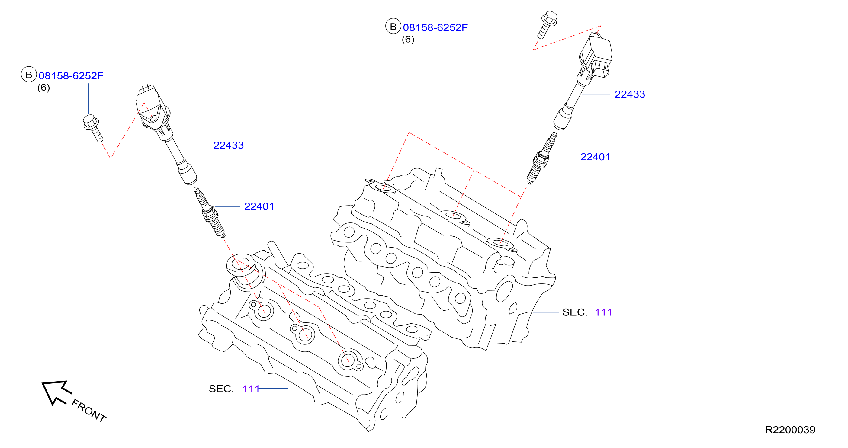
The 2006 Nissan Altima uses a coil-on-plug (COP) ignition system. This means that each cylinder has its own dedicated ignition coil that sits directly on top of the spark plug. This configuration eliminates the need for spark plug wires (also known as high-tension leads), which reduces energy loss and improves ignition performance.
Specifically, the 2006 Altima's ignition coil system varies depending on the engine. The two most common engines are:
- 2.5L QR25DE Inline-4 Engine: This engine has four ignition coils, one for each cylinder.
- 3.5L VQ35DE V6 Engine: This engine has six ignition coils, one for each cylinder.
Regardless of the engine type, the fundamental principles and wiring connections remain similar for each coil. Let's examine a generic COP ignition coil diagram that is generally applicable to the 2006 Altima:
Generic COP Ignition Coil Diagram (Applicable to 2006 Altima)
While the specific wire colors may vary slightly depending on the exact year and sub-model, the functionality of the connections remains consistent. A typical COP ignition coil will have the following connections:
- Battery Voltage (12V): This provides the coil with the initial power source. It's typically a fused connection, meaning there's a fuse in the circuit to protect the system from overcurrent. Often this connection is a red or white wire.
- Ground: Provides the return path for the electrical current. This is crucial for completing the circuit. Usually, a black or brown wire.
- Ignition Trigger Signal (from ECM): This is the signal from the ECM that tells the coil when to fire. The ECM controls this signal based on inputs from the crankshaft and camshaft position sensors. The wire color for this signal varies, and it's crucial to consult the specific wiring diagram for your Altima's engine.
It's important to note that these connections are typically within a connector that plugs directly into the ignition coil. To access these connections for testing or troubleshooting, you'll need to disconnect the connector.
Specific Wiring Considerations for the 2.5L and 3.5L Engines
While the generic diagram provides a good overview, you'll need to consult the specific wiring diagrams for the 2.5L QR25DE and 3.5L VQ35DE engines for precise wire colors and connector locations. These diagrams are usually available in the vehicle's repair manual or online databases. Websites like AlldataDIY and Mitchell OnDemand provide detailed wiring schematics for specific vehicle models.
Here's what you can typically expect:
- 2.5L QR25DE: The 2.5L engine will have four identical ignition coils. The wiring to each coil will be very similar, with the exception of the ignition trigger signal wire, which will be unique for each cylinder to ensure proper firing sequence.
- 3.5L VQ35DE: The 3.5L engine will have six identical ignition coils. Similar to the 2.5L, the wiring will be consistent across all coils, except for the individual ignition trigger signal wires controlled by the ECM.
Troubleshooting Ignition Coil Issues
A failing ignition coil can manifest in several symptoms, including:
- Misfires: This is the most common symptom. A misfire occurs when one or more cylinders fail to fire properly, resulting in a rough-running engine, decreased power, and poor fuel economy.
- Check Engine Light: The ECM will often detect a misfire and illuminate the check engine light. Diagnostic trouble codes (DTCs) such as P0300 (Random Misfire), P0301 (Misfire Cylinder 1), P0302 (Misfire Cylinder 2), etc., may be stored.
- Rough Idle: The engine may idle roughly or stall.
- Decreased Fuel Economy: A misfiring cylinder wastes fuel, leading to reduced fuel efficiency.
- Lack of Power: The engine may feel sluggish and lack its usual power.
If you suspect an ignition coil issue, the following troubleshooting steps can be helpful:
- Read Diagnostic Trouble Codes (DTCs): Use an OBD-II scanner to retrieve any stored DTCs. This will provide valuable clues about which cylinder is misfiring.
- Visual Inspection: Inspect the ignition coils for any signs of damage, such as cracks, melted plastic, or corrosion. Check the wiring connectors for loose connections or damaged wires.
- Coil Swapping: If you have a misfire on a specific cylinder, try swapping the ignition coil from that cylinder with a known good coil from another cylinder. Clear the DTCs and see if the misfire follows the coil to the new cylinder. If it does, then the coil is likely faulty.
- Multimeter Testing: You can use a multimeter to test the primary and secondary resistance of the ignition coil. Compare the readings to the manufacturer's specifications. A significant deviation from the specified resistance indicates a faulty coil. Testing for voltage at the coil connector when the ignition is on is also useful.
- Spark Test: With the coil disconnected, it is possible to use an inline spark tester to confirm spark is being produced when the engine is cranked. This should only be performed by a trained technician.
Safety Precautions
Working with electrical components in a vehicle can be dangerous. Always take the following precautions:
- Disconnect the Battery: Before working on any electrical components, disconnect the negative terminal of the battery to prevent accidental short circuits or electric shocks.
- Use Proper Tools: Use insulated tools to avoid electrical shocks.
- Consult the Repair Manual: Always refer to the vehicle's repair manual for specific instructions and safety precautions.
Conclusion
The 2006 Nissan Altima's ignition system, with its coil-on-plug design, represents a significant advancement in automotive technology. Understanding the ignition coil diagram, including the wiring connections and their functions, is essential for effective troubleshooting and maintenance. By following the steps outlined in this guide and exercising proper safety precautions, you can diagnose and repair ignition coil issues, ensuring the smooth and efficient operation of your Altima's engine. Remember to always consult the specific wiring diagrams for your vehicle model for accurate information and to use caution when working with electrical components.