2006 Nissan Sentra Climate Control Unit
Delving into the inner workings of a modern vehicle often reveals a surprising level of complexity, even in seemingly simple systems. This article dissects the climate control unit of a 2006 Nissan Sentra, offering a comprehensive look at its components, operation, and the principles governing its performance. We'll explore the electromechanical components and the control logic that enables it to maintain a comfortable cabin environment.
The Foundation: Refrigerant Cycle and Airflow
At its core, the 2006 Sentra's climate control, like most automotive systems, relies on the principles of the refrigerant cycle and controlled airflow. The refrigerant cycle, utilizing R-134a in this case, is a thermodynamic process that extracts heat from the cabin air and rejects it outside the vehicle. The airflow system then distributes this cooled (or heated) air to the desired vents.
The refrigerant cycle consists of four key components: the compressor, condenser, expansion valve (or orifice tube, depending on the specific configuration), and evaporator.
- Compressor: Driven by the engine, the compressor increases the pressure and temperature of the refrigerant vapor. This high-pressure, high-temperature vapor is then sent to the condenser.
- Condenser: Located typically in front of the radiator, the condenser dissipates heat from the high-pressure refrigerant vapor, causing it to condense into a high-pressure liquid. Airflow across the condenser fins facilitates this heat exchange.
- Expansion Valve/Orifice Tube: This component meters the flow of high-pressure liquid refrigerant into the evaporator. As the refrigerant passes through, it experiences a rapid pressure drop, causing it to partially vaporize and significantly decrease in temperature.
- Evaporator: Located inside the HVAC (Heating, Ventilation, and Air Conditioning) unit within the dashboard, the evaporator is a finned heat exchanger where the cold, low-pressure refrigerant absorbs heat from the air flowing across it. This cools the air before it's distributed into the cabin. The refrigerant, now a low-pressure vapor, returns to the compressor to begin the cycle anew.
The airflow system is equally crucial. A blower motor, typically a squirrel-cage fan, forces air through the HVAC unit. This air can be drawn from outside the vehicle (fresh air mode) or recirculated from within the cabin (recirculation mode). Dampers, or flaps, strategically positioned within the HVAC unit control the direction of airflow, determining whether it passes through the evaporator (for cooling), the heater core (for heating), or bypasses both (for ventilation).
The Climate Control Unit: The Brains of the Operation
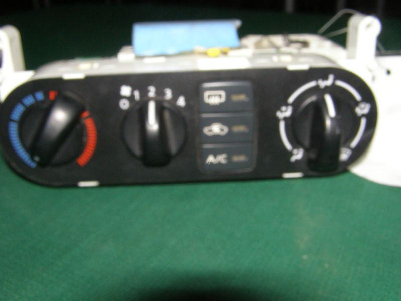
The climate control unit, specifically the control panel on the dashboard, serves as the interface between the driver and the HVAC system. It houses the controls for adjusting temperature, fan speed, airflow direction, and mode of operation (A/C, heat, defrost, etc.). However, it's more than just a simple switchboard; it's a sophisticated electronic control module that interprets the driver's inputs and translates them into commands for the various actuators within the HVAC system.
Components of the Control Unit:
- User Interface: This includes the buttons, knobs, and displays that allow the driver to interact with the system. These controls are connected to potentiometers, encoders, or simple switches that provide electrical signals to the control module.
- Microcontroller: The heart of the climate control unit is a microcontroller. This small computer processes the input signals from the user interface, temperature sensors, and other inputs to determine the desired settings for the HVAC system. It then generates output signals to control the various actuators.
- Sensors: Several sensors provide feedback to the microcontroller. These include:
- Interior Temperature Sensor: Measures the temperature inside the cabin.
- Outside Temperature Sensor: Measures the ambient temperature outside the vehicle.
- Evaporator Temperature Sensor: Monitors the temperature of the evaporator core to prevent it from freezing.
- Engine Coolant Temperature Sensor: Provides information about engine temperature, which is used to regulate the heater core output.
- Actuators: These are electromechanical devices that physically adjust the HVAC system components based on the microcontroller's commands. Common actuators include:
- Blower Motor Resistor/Control Module: Controls the speed of the blower motor, allowing the driver to adjust the airflow volume. On some models, a dedicated control module may replace the traditional resistor pack for more precise and efficient control.
- Mode Door Actuator: Controls the position of the mode door, which directs airflow to the different vents (dash, floor, defrost).
- Blend Door Actuator: Controls the position of the blend door, which regulates the proportion of air that passes through the heater core, thus controlling the air temperature.
- Recirculation Door Actuator: Controls the position of the recirculation door, determining whether air is drawn from outside the vehicle or recirculated from within.
- A/C Compressor Clutch Relay: Engages and disengages the A/C compressor clutch, turning the air conditioning system on or off.
- Communication Bus: The climate control unit communicates with other vehicle systems, such as the engine control unit (ECU) and body control module (BCM), via a communication bus (typically CAN bus). This allows it to receive information about engine speed, vehicle speed, and other parameters that may affect climate control performance.
Operational Logic and Feedback Loops
The climate control unit operates based on a series of complex algorithms and feedback loops. The microcontroller continuously monitors the inputs from the sensors and the user interface, and adjusts the actuators to maintain the desired cabin temperature and airflow. For example, if the driver sets the temperature to 72°F and the interior temperature sensor reports that the cabin is currently 80°F, the microcontroller will activate the A/C compressor, increase the blower motor speed, and adjust the blend door to allow more air to pass through the evaporator. As the cabin temperature approaches the set point, the microcontroller will gradually reduce the cooling output to maintain a stable temperature.
Feedback loops are critical for maintaining accurate and stable climate control. The interior temperature sensor provides feedback to the microcontroller, allowing it to adjust the cooling or heating output based on the actual cabin temperature. The evaporator temperature sensor prevents the evaporator core from freezing by cycling the A/C compressor on and off as needed. The engine coolant temperature sensor ensures that the heater core is not activated until the engine has warmed up sufficiently.
Furthermore, the system often incorporates adaptive control strategies. For example, the climate control unit may adjust its cooling or heating output based on the intensity of sunlight hitting the vehicle's cabin, compensating for solar heat gain. It might also adjust the airflow distribution based on vehicle speed, ensuring optimal comfort at both low and high speeds.
Troubleshooting and Diagnostics
Understanding the components and operation of the climate control unit is essential for effective troubleshooting. Common problems include:
- A/C Not Cooling: This could be caused by a refrigerant leak, a faulty compressor, a clogged condenser, or a malfunctioning expansion valve.
- Heater Not Working: This could be caused by a low coolant level, a faulty thermostat, a clogged heater core, or a malfunctioning blend door actuator.
- Blower Motor Not Working: This could be caused by a faulty blower motor, a blown fuse, a bad blower motor resistor, or a problem with the blower motor control module.
- Incorrect Airflow Direction: This is typically caused by a malfunctioning mode door actuator.
Modern diagnostic tools can greatly simplify the troubleshooting process. Many scan tools can communicate with the climate control unit and retrieve diagnostic trouble codes (DTCs), which provide valuable clues about the nature and location of the problem. Some scan tools can also activate the actuators and monitor the sensor readings, allowing technicians to pinpoint the source of the problem quickly.
In conclusion, the 2006 Nissan Sentra's climate control unit represents a significant advancement in automotive comfort technology. By understanding the principles of the refrigerant cycle, the airflow system, and the electronic control logic, we can gain a deeper appreciation for the engineering that goes into creating a comfortable and enjoyable driving experience. Furthermore, this knowledge empowers us to diagnose and repair problems with greater confidence, ensuring that our vehicles continue to provide the comfort and convenience we expect.