2015 Nissan Nv200 A/c Relay Location
The 2015 Nissan NV200, a compact cargo van, provides a practical solution for businesses needing efficient transport. One essential component for driver and passenger comfort, especially in warmer climates, is the air conditioning system. Understanding the location and function of the A/C relay is crucial for troubleshooting cooling issues. This guide dives deep into pinpointing the A/C relay within a 2015 NV200, elucidating its role, and offering insights into associated electrical diagnostics.
Understanding the A/C System's Electrical Circuit
Before diving into the specific location, it's beneficial to grasp the basics of the A/C system's electrical operation. The A/C system is not a single, self-contained unit. It's an intricately linked system requiring signals from various sensors and components. The relay acts as an electrical switch, allowing a small control signal to activate a circuit that draws a larger current. In the context of the A/C, this relay controls the power to the A/C compressor clutch, which engages the compressor, beginning the cooling process. The relay receives a signal from the vehicle's Engine Control Module (ECM), often referred to as the Powertrain Control Module (PCM), based on inputs from the A/C request switch inside the cabin, the temperature sensor, and the pressure sensor. The ECM will only engage the compressor clutch if all conditions are met: the A/C is requested, the engine is running, the system pressure is within the correct range, and the engine temperature is not excessively high.
Locating the A/C Relay in the 2015 Nissan NV200
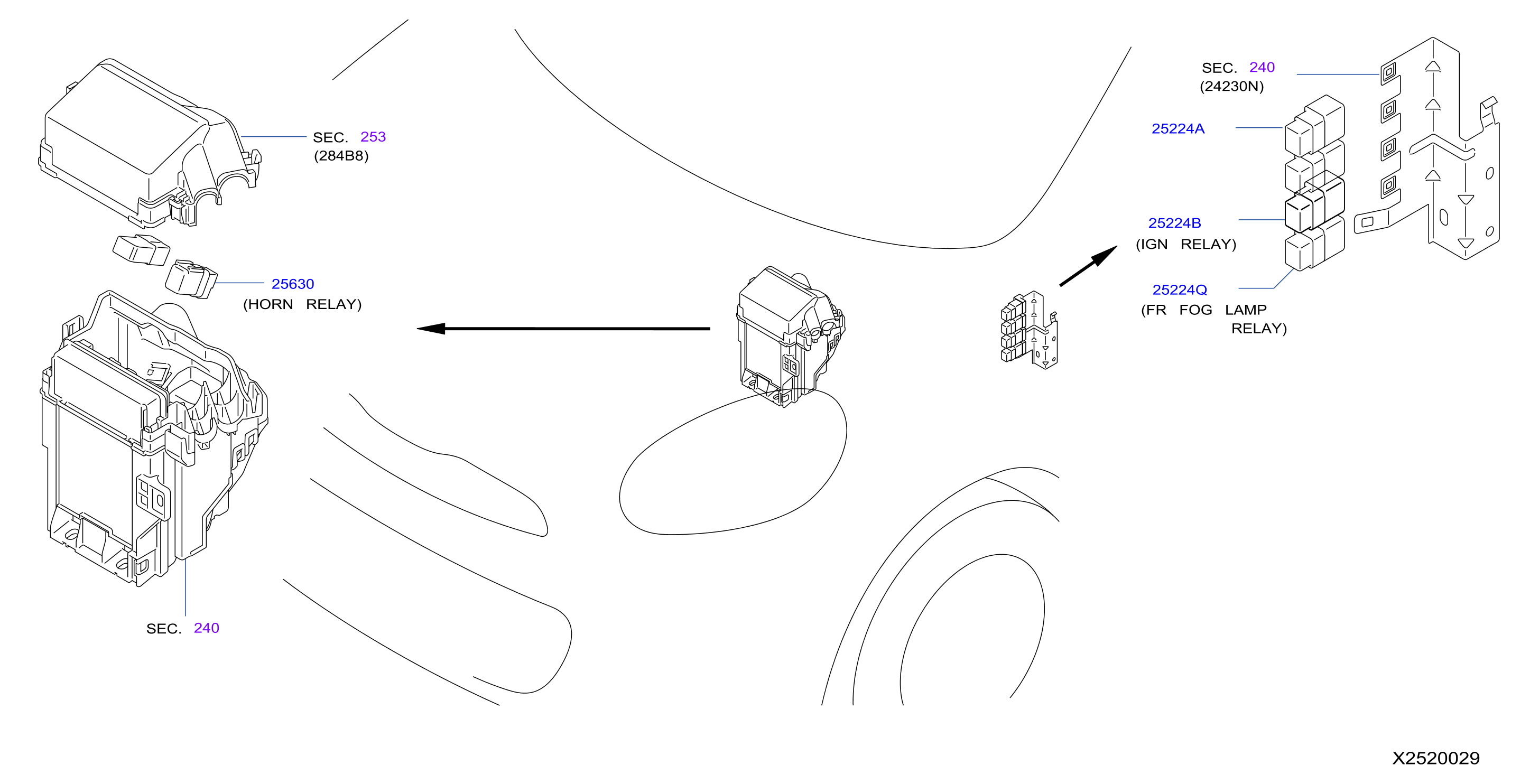
The A/C relay in the 2015 Nissan NV200 is typically found within the engine compartment's fuse and relay box. This box, often black plastic and labeled with a diagram, houses numerous relays and fuses that protect and control various electrical circuits throughout the vehicle. The precise location of the A/C relay within this box can be determined by consulting the vehicle's owner's manual or a detailed repair manual specific to the 2015 NV200. However, there are common areas to start your search:
Primary Fuse and Relay Box Location
The primary fuse and relay box is almost universally located close to the battery, often on either the driver's side or passenger's side of the engine compartment. Look for a rectangular black box with a hinged or clip-on lid. Carefully open the lid to reveal the fuses and relays.
Identifying the A/C Relay
Once the fuse and relay box is open, the next step is to identify the correct relay. This is where the owner's manual or a repair manual becomes invaluable. The inside of the fuse box lid often contains a diagram indicating the function of each fuse and relay. Look for labels like "A/C Relay," "Air Conditioning Relay," or sometimes a symbol representing an A/C unit (a snowflake).
If a diagram isn't readily available, you can use a process of elimination and visual inspection. Relays are typically small, cube-shaped components, often black or gray in color. Try comparing the relay with other relays in the box. Look for relays with similar markings or pin configurations to the A/C relay (if you can find a known good A/C relay from another vehicle, for instance).
It is crucial to disconnect the negative battery terminal before attempting to remove or replace any fuses or relays. This precaution minimizes the risk of electrical shock and prevents accidental short circuits that could damage the vehicle's electrical system.
Common Relay Layouts and Pin Configurations
While specific layouts can vary, automotive relays generally adhere to a standard pin configuration. The most common is a four- or five-pin setup. Understanding these pins can aid in diagnosing relay issues:
- Pin 30: This pin is the main power input to the relay. It is connected directly to the battery through a fuse.
- Pin 85: This pin is one side of the relay coil. It receives a ground signal when the ECM wants to activate the A/C.
- Pin 86: This pin is the other side of the relay coil. It receives a positive signal from the ignition or ECM.
- Pin 87: This pin is the output that provides power to the A/C compressor clutch when the relay is activated (closed).
- Pin 87a (Optional): This pin is a normally closed contact. It is connected to Pin 30 when the relay is not activated and disconnects when the relay is activated. This is less commonly used in A/C systems.
Troubleshooting A/C Relay Issues
Suspect the A/C relay if the A/C system is not functioning and other common issues like low refrigerant levels or a faulty A/C compressor have been ruled out. Here are some troubleshooting steps:
Visual Inspection
Visually inspect the relay for any signs of damage, such as cracks, melted plastic, or corrosion on the pins. A damaged relay should be replaced immediately.
Relay Swap Test
A simple test is to swap the A/C relay with a known good relay of the same type. For example, you could swap it with the horn relay (assuming the horn is working) or another non-essential relay. If the A/C starts working after the swap, then the original relay is likely faulty. Ensure the replacement relay has the exact same specifications and amperage rating.
Multimeter Testing
A multimeter can be used to test the functionality of the relay. Here's how:
- Continuity Test: Disconnect the relay and use the multimeter to check for continuity between pins 30 and 87 (or 87a, if present) when the relay is not energized. If there is continuity between 30 and 87 when the relay is not powered, the relay is shorted and must be replaced. Similarly, test continuity between pins 85 and 86. There should be continuity because those two points are a coil of wire. No continuity indicates a broken coil.
- Voltage Test: Reconnect the relay and turn the ignition to the "ON" position (engine not running). Use the multimeter to check for voltage at pin 86 (the coil positive) and ground at pin 85 (the coil negative). If voltage and ground are present, the ECM is sending the signal to activate the relay. If either are missing, the problem lies upstream, possibly with the A/C request switch, pressure sensor, temperature sensor, wiring, or the ECM itself.
- Relay Activation Test: If voltage and ground are present at the coil, you can test if the relay is physically switching. Connect the multimeter to pins 30 and 87. With the A/C system engaged, you should measure battery voltage when the relay activates. If there is no voltage, even though voltage and ground are at the coil pins, the relay itself is faulty and needs replacement.
Related Components and Considerations
When troubleshooting A/C issues, consider these related components:
- A/C Compressor Clutch: The A/C relay provides power to the clutch. If the clutch is faulty, even a working relay won't engage the compressor.
- A/C Pressure Switch: This switch prevents the compressor from engaging if the refrigerant pressure is too high or too low, protecting the system. A faulty pressure switch can prevent the relay from activating.
- Refrigerant Level: Insufficient refrigerant will prevent the compressor from engaging.
- Fuses: A blown fuse in the A/C circuit can prevent the relay from receiving power.
- Wiring: Damaged or corroded wiring can cause intermittent or complete failure of the A/C system.
- Engine Control Module (ECM): The ECM controls the A/C system based on inputs from various sensors. A faulty ECM can prevent the A/C relay from activating.
Conclusion
Locating and understanding the function of the A/C relay in a 2015 Nissan NV200 is essential for diagnosing and resolving A/C system issues. By following the steps outlined in this guide, curious readers and amateur engineers can gain valuable insights into the vehicle's electrical system and potentially save time and money on repairs. Remember to always prioritize safety by disconnecting the battery before working on electrical components and consulting a qualified mechanic if you are unsure about any aspect of the troubleshooting process.