5-lug Conversion Hub Specifications And Bearing Load Calculations
The quest for improved performance and aesthetics often leads automotive enthusiasts down the path of modifications. Among these, the 5-lug conversion stands out as a popular upgrade, enhancing braking power, wheel selection, and overall vehicle stability. But beyond the visual appeal lies a complex interplay of engineering principles. This article delves into the technical aspects of 5-lug conversion hub specifications and, crucially, bearing load calculations, offering a detailed understanding for both curious readers and amateur engineers.
Understanding Hub Specifications in a 5-Lug Conversion
A successful 5-lug conversion isn't simply about bolting on new wheels. It requires careful consideration of hub specifications to ensure proper fitment, functionality, and safety. Let's dissect the key parameters:
Bolt Pattern
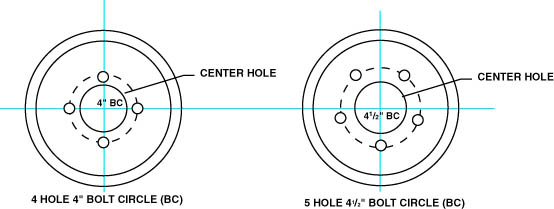
The bolt pattern, often expressed as "5x114.3" or "5x4.5" (in inches), dictates the number of lug nuts (five in this case) and the diameter of the circle they form. Selecting the correct bolt pattern is paramount. Mismatched patterns prevent proper wheel mounting, leading to catastrophic failures.
Hub Centric vs. Lug Centric
Hub-centric wheels rely on the center bore of the wheel fitting snugly over the hub's pilot diameter for centering. This method evenly distributes the vehicle's weight across the hub. Lug-centric wheels, conversely, rely solely on the lug nuts for centering. While both methods can work, hub-centric setups are generally preferred, especially for high-performance applications, as they minimize vibration and stress on the lug studs.
When performing a conversion, consider adapting to a hub-centric design for optimal performance. If switching to lug-centric, ensure high-quality lug nuts and meticulous installation.
Hub Flange Diameter and Offset
The hub flange diameter is the diameter of the surface where the wheel mounts. It must be compatible with the wheel's mounting surface. Closely related is the concept of offset or wheel backspacing. This refers to the distance between the wheel's mounting surface and its centerline. Incorrect offset can lead to tire rubbing against the suspension components or fenders, affecting steering and handling. 5-lug conversions often require adjustments to offset to accommodate wider wheels or different suspension geometry.
Bearing Journal Diameter and Width
This is where the bearing sits and is crucial for bearing selection and load capacity. If the bearing journal diameter and width of the new hub differ significantly from the original, custom bearings or hub carriers may be needed. Precise measurements are vital; even minor discrepancies can lead to premature bearing failure.
Material and Manufacturing Process
The material used in hub construction directly impacts its strength and durability. Forged aluminum and high-grade steel are common choices. The manufacturing process, such as forging or casting, also influences the hub's structural integrity. For high-performance applications, forged hubs are generally preferred due to their superior strength-to-weight ratio. The heat treatment is also important. Look for hubs that have undergone proper heat treatment to increase their strength and resistance to wear.
Bearing Load Calculations: The Heart of a Safe Conversion
Simply choosing the right bolt pattern isn't enough. The bearings within the hub must be capable of handling the increased loads resulting from wider tires, different wheel offsets, and potentially, increased braking forces. Understanding bearing load calculations is, therefore, essential for a safe and reliable 5-lug conversion.
Types of Loads
Bearings in a wheel hub experience two primary types of loads:
- Radial Load: This is the force acting perpendicular to the bearing's axis of rotation, primarily due to the vehicle's weight.
- Axial (Thrust) Load: This force acts parallel to the bearing's axis of rotation, arising from cornering forces, braking, and road imperfections.
Factors Influencing Bearing Load
Several factors contribute to the magnitude of these loads:
- Vehicle Weight: A heavier vehicle places greater radial load on the bearings.
- Wheel Offset: Increased offset effectively extends the lever arm, increasing the bending moment on the hub and consequently, the loads on the bearings. A larger negative offset (wheel protruding further outwards) places a greater load on the outer bearing.
- Tire Size and Grip: Wider tires and stickier compounds generate higher cornering forces, increasing both radial and axial loads.
- Braking Force: Aggressive braking maneuvers can introduce significant axial loads. Larger brake rotors and calipers also increase the leverage force.
- Road Conditions: Uneven surfaces and potholes impart impact loads, momentarily exceeding normal operating loads.
Calculating Radial Load
A simplified approach to estimating radial load involves dividing the vehicle's weight by the number of wheels. However, this only provides a baseline. A more accurate calculation considers weight distribution and dynamic load transfer during acceleration, braking, and cornering. Here's a breakdown:
Static Radial Load (Frs): This is the load on the bearing when the vehicle is stationary. It can be approximated as:
Frs = (Vehicle Weight / Number of Wheels) * Weight Distribution Factor
The Weight Distribution Factor accounts for unequal weight distribution between the front and rear axles.
Dynamic Radial Load (Frd): This considers the additional load imposed during vehicle operation. This is more complex and needs to consider acceleration, braking and cornering factors.
Frd = Frs * Dynamic Load Factor
The Dynamic Load Factor typically ranges from 1.2 to 2.5 or higher, depending on driving style and road conditions. A value of 1.5 is a reasonable starting point for street use, while aggressive driving or track use may warrant a higher factor.
Calculating Axial Load
Estimating axial load is more challenging due to the complex interplay of factors during cornering and braking. One simplified method uses the following equation:
Axial Load (Fa):
Fa = (Cornering Force * Hub Offset) / Wheelbase
Where:
- Cornering Force is estimated based on the vehicle's cornering stiffness and lateral acceleration.
- Hub Offset is the distance between the wheel mounting surface and the bearing centerline.
- Wheelbase is the distance between the front and rear axles.
This equation provides a rough estimate and assumes constant cornering force. More sophisticated calculations involve detailed simulations and data acquisition.
Bearing Selection and Life Expectancy
Once the radial and axial loads are estimated, the appropriate bearing can be selected. Bearing manufacturers provide load ratings (static and dynamic) for their bearings. These ratings represent the maximum load the bearing can withstand for a specified number of revolutions (usually millions). The bearing life expectancy can be estimated using these ratings and the calculated loads. Ensure that the bearing's dynamic load rating significantly exceeds the calculated dynamic radial load, especially when considering the axial load component.
Manufacturers frequently publish bearing life calculation formulas, often involving factors like application temperature, lubrication quality, and desired reliability. It is recommended to consult bearing manufacturer catalogs or engineering resources for detailed calculations and guidelines.
Important Consideration: Remember that these are simplified calculations. For critical applications, consult with a qualified engineer to perform a comprehensive bearing load analysis.
Practical Considerations for 5-Lug Conversions
- OEM vs. Aftermarket Hubs: If possible, opt for OEM (Original Equipment Manufacturer) hubs from a vehicle with a similar weight and performance profile that already utilizes a 5-lug configuration. This often simplifies bearing selection and ensures compatibility with existing suspension components.
- Bearing Upgrades: Consider upgrading to high-performance bearings with increased load capacity and durability. Ceramic hybrid bearings, while more expensive, offer reduced friction and improved heat dissipation.
- Regular Inspection: After performing a 5-lug conversion, regularly inspect the wheel bearings for signs of wear or play. Early detection of bearing issues can prevent catastrophic failures.
- Proper Installation: Accurate installation of the hub and bearings is crucial. Use proper tools and techniques to avoid damaging the bearings during installation. Follow the manufacturer's torque specifications meticulously.
In conclusion, a 5-lug conversion is more than just a cosmetic upgrade. It's an engineering modification that requires a thorough understanding of hub specifications and bearing load calculations. By carefully considering these factors, enthusiasts can ensure a safe, reliable, and performance-enhancing modification.