98 Nissan Frontier Instrument Cluster
The instrument cluster, or gauge cluster, is the central nervous system of information delivery within a vehicle. It's the driver's primary interface for understanding the vehicle's operating parameters, from speed and engine RPM to fuel level and system warnings. While modern vehicles boast increasingly complex digital displays, the 1998 Nissan Frontier’s instrument cluster represents a robust and relatively straightforward example of electromechanical instrumentation. This article will dissect the inner workings of this cluster, offering insights into its design, functionality, and potential points of failure.
Overview of the 1998 Nissan Frontier Instrument Cluster
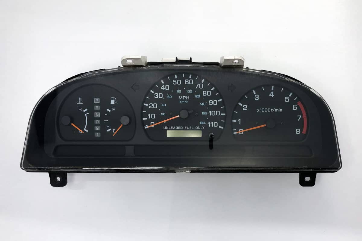
The 1998 Nissan Frontier’s instrument cluster is a self-contained unit housing several critical gauges and indicators. These typically include:
- Speedometer: Indicates the vehicle's speed in miles per hour (MPH) and kilometers per hour (km/h).
- Tachometer: Displays the engine's rotational speed in revolutions per minute (RPM).
- Fuel Gauge: Shows the level of fuel remaining in the tank.
- Temperature Gauge: Monitors the engine coolant temperature.
- Warning Lights: A series of indicators that illuminate to alert the driver to potential problems with various vehicle systems (e.g., check engine, oil pressure, battery, brake).
Unlike some more advanced systems, the '98 Frontier's cluster relies heavily on analog gauges. This means physical needles move across calibrated scales to represent the measured values. These needles are actuated by electromechanical devices, combining electrical signals with mechanical movement.
Dissecting the Components and Their Functions
Speedometer
The speedometer in the '98 Frontier typically uses a magnetic induction principle. A rotating cable, driven by the vehicle's transmission, connects to a permanent magnet inside the speedometer housing. As the cable spins, so does the magnet. This rotating magnet induces eddy currents in a nearby aluminum cup. The eddy currents create their own magnetic field, which interacts with the field of the permanent magnet. This interaction causes the aluminum cup to rotate. The cup is attached to the speedometer needle via a hairspring. The hairspring provides resistance to the cup's rotation. The faster the cable spins, the stronger the induced magnetic field, the further the cup rotates, and the higher the speedometer reading.
Calibration is crucial for accurate speed readings. This is achieved by adjusting the strength of the hairspring. A weaker spring will result in a higher reading for a given cable speed, while a stronger spring will result in a lower reading.
Tachometer
The tachometer measures the engine's RPM. In the '98 Frontier, this is typically done using an electrical signal from the ignition system. The ignition coil fires each time a spark plug ignites the air-fuel mixture. This firing event generates a voltage pulse. The tachometer counts these pulses over a specific time period. The frequency of these pulses is directly proportional to the engine's RPM. Inside the tachometer, a circuit converts these pulses into a corresponding current that drives a small electromagnet. The electromagnet interacts with a pivoted needle, causing it to move across the RPM scale. A hairspring provides restoring force, similar to the speedometer.
Troubleshooting a faulty tachometer often involves checking the wiring connections to the ignition coil and the tachometer itself. A weak or intermittent signal from the ignition coil can cause erratic readings.
Fuel Gauge
The fuel gauge system relies on a sender unit located inside the fuel tank and the gauge itself in the instrument cluster. The sender unit typically consists of a float attached to a variable resistor (potentiometer). As the fuel level changes, the float moves up or down, changing the resistance of the potentiometer. This resistance change alters the current flowing through a circuit. The fuel gauge within the instrument cluster is essentially a galvanometer. The current from the sender unit passes through a coil in the galvanometer, creating a magnetic field. This field interacts with a permanent magnet, causing the gauge needle to deflect. Higher current indicates a higher fuel level, and vice versa.
Common problems with the fuel gauge include a faulty sender unit (e.g., a stuck float or a damaged potentiometer) or a wiring issue between the sender unit and the gauge.
Temperature Gauge
The temperature gauge operates on a similar principle to the fuel gauge, using a temperature sensor (thermistor) located in the engine coolant passage. The thermistor's resistance changes with temperature. As the coolant temperature rises, the thermistor's resistance decreases, allowing more current to flow through the gauge. This increased current deflects the needle on the temperature gauge, indicating a higher temperature. The gauge itself is, again, a galvanometer driven by the current flowing through it.
A common issue with the temperature gauge is a faulty thermistor. Also, check for wiring problems between the thermistor and the gauge.
Warning Lights
The warning lights are simple indicators that illuminate when a specific condition is met. These lights are typically controlled by sensors located throughout the vehicle. For example, the oil pressure warning light is activated by a pressure switch that closes when the oil pressure drops below a certain level. This completes the circuit, illuminating the warning light. Similarly, the check engine light is triggered by the engine control unit (ECU) when it detects a fault in the engine management system.
These lights are usually simple incandescent bulbs or LEDs. Diagnosing issues with warning lights involves identifying the specific circuit that is triggering the light and then troubleshooting the sensor or system associated with that circuit.
Power Supply and Grounding
The entire instrument cluster requires a stable power supply and reliable grounding to function correctly. The cluster typically receives power from the vehicle's battery via the ignition switch. A dedicated fuse protects the cluster from overcurrent. Grounding is equally important. A poor ground connection can cause erratic gauge readings or prevent the cluster from functioning altogether. Ensure all ground connections are clean and secure.
Troubleshooting Common Issues
Several common problems can affect the performance of the '98 Nissan Frontier's instrument cluster:
- Dead Gauges: This often indicates a problem with the power supply, ground connection, or the gauge itself. Check the fuse, wiring, and ground connections. If those are good, the gauge may be faulty and require replacement.
- Erratic Readings: This can be caused by a faulty sensor, a wiring problem, or a failing gauge. Use a multimeter to check the sensor output and the wiring connections.
- Dim or Flickering Lights: This is often due to loose connections, corroded contacts, or failing bulbs. Inspect the bulb sockets and wiring connectors.
- Inaccurate Speedometer: Check the speedometer cable for damage or kinks. If the cable is good, the speedometer itself may be faulty.
When troubleshooting the instrument cluster, always refer to the vehicle's service manual for specific wiring diagrams and testing procedures.
Conclusion
The 1998 Nissan Frontier's instrument cluster, while not as sophisticated as modern digital displays, provides a reliable and understandable interface for monitoring vehicle performance. By understanding the underlying principles of operation and the potential points of failure, owners and enthusiasts can effectively diagnose and repair issues, ensuring accurate and reliable information delivery for years to come. The combination of electromechanical components and basic electrical circuits makes it a valuable learning tool for anyone interested in automotive technology. The simplicity allows for easy understanding and the ability to troubleshoot common problems. Although replacement clusters are often available, understanding the internal workings can potentially save time and money through targeted repairs.