A Detailed Fuse And Relay Diagram For The 240sx Chassis
Alright, let's dive deep into the fuse and relay situation for your 240SX (S13/S14 chassis). Understanding these components is crucial for troubleshooting electrical gremlins and safely modifying your ride. This isn't just about replacing a blown fuse; it's about knowing *why* it blew and how the system is designed to protect your car's delicate electrical circuits.
Understanding Fuses: The First Line of Defense
A fuse is a safety device containing a thin wire that melts and breaks the circuit when excessive current flows through it. This prevents damage to more expensive components downstream. Think of it as a sacrificial lamb protecting your car's electrical system.
Fuses are rated in *amperes* (amps), indicating the amount of current they can handle before blowing. Using a fuse with a higher amperage rating than specified is extremely dangerous because it can allow too much current to flow, potentially causing a fire. Always replace a blown fuse with one of the same rating.
Fuse Box Locations and Diagrams
The 240SX typically has two main fuse box locations:
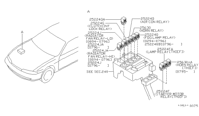
- Engine Bay Fuse Box: Located near the battery, this fuse box houses fuses for critical engine management systems, headlights, and other essential functions.
- Interior Fuse Box: Usually located under the driver's side dashboard, this fuse box controls interior lighting, radio, power windows/locks, and other comfort features.
It's absolutely essential to consult your 240SX's repair manual (FSM - Factory Service Manual) for precise fuse and relay locations and amperage ratings. While the general layout is similar across models and years, subtle differences can exist.
However, to give you a general idea, let's outline some commonly found fuses and their typical function. Remember, this is NOT a substitute for your car's specific diagram:
Engine Bay Fuse Box (Example):
FUSE | AMPERAGE | CIRCUIT(S) PROTECTED
ALT | 80A | Alternator
IGN | 15A | Ignition System
HEAD (LO) | 15A | Low Beam Headlights
HEAD (HI) | 15A | High Beam Headlights
EGI | 10A | Engine Control Unit (ECU)
FUEL PUMP | 15A | Fuel Pump
COOLING FAN | 30A | Cooling Fan Motor
Interior Fuse Box (Example):
FUSE | AMPERAGE | CIRCUIT(S) PROTECTED
ROOM LAMP | 10A | Interior Lights, Clock, Radio (some circuits)
HAZARD | 15A | Hazard Lights
TURN SIGNAL | 10A | Turn Signals
WIPER | 20A | Windshield Wiper Motor
POWER WINDOW | 20A | Power Window Motors
POWER LOCK | 10A | Power Door Locks
CIGAR LIGHTER | 10A | Cigar Lighter/Accessory Power
Troubleshooting Blown Fuses:
- Identify the Blown Fuse: Visually inspect the fuse. A blown fuse will have a broken filament inside. You can also use a multimeter to check for continuity across the fuse.
- Replace the Fuse: Replace it with a fuse of the exact same amperage.
- Test the Circuit: After replacing the fuse, turn on the component or system the fuse protects. If the fuse blows again immediately, you have a short circuit that needs to be diagnosed.
- Locate the Short: A short circuit is a low-resistance path that allows excessive current to flow. Common causes include damaged wiring, faulty components, or exposed wires touching ground. Locating a short can be time-consuming and may require specialized tools like a circuit tester.
Relays: Switching High-Current Circuits with Low-Current Signals
A relay is an electrically operated switch. It uses a small current to control a larger current. Think of it as a gatekeeper: a small signal tells it to open or close a gate, allowing a much larger flow of power through. Relays are used to control components that require a lot of current, such as headlights, fuel pumps, and cooling fans, without requiring heavy-duty switches in the dashboard.
A typical automotive relay has five terminals:
- 30: Battery power (typically fused).
- 85: Ground connection.
- 86: Trigger signal (positive or negative, depending on the relay type). This is the low-current signal that activates the relay.
- 87: Normally Open (N.O.) contact. The circuit is open (disconnected) until the relay is activated.
- 87a: Normally Closed (N.C.) contact. The circuit is closed (connected) until the relay is activated. (Not always present)
Relay Locations and Functions
Relays are often located in the same fuse boxes as the fuses, but they can also be found in separate relay boxes or mounted individually. Again, consult your FSM for precise locations.
Here are some common relays and their functions in a 240SX:
- Fuel Pump Relay: Controls power to the fuel pump.
- Headlight Relay: Controls power to the headlights (high and low beams).
- Cooling Fan Relay: Controls power to the cooling fan motor.
- Starter Relay: Controls power to the starter solenoid.
- A/C Relay: Controls power to the air conditioning compressor clutch.
Testing Relays
You can test a relay using a multimeter and a 12V power source.
- Continuity Test (Coil): Disconnect the relay. Use a multimeter to check for continuity between terminals 85 and 86. You should see a low resistance reading (e.g., 70-120 ohms). If you see no continuity, the coil is likely open and the relay is bad.
- Activation Test: Apply 12V to terminal 86 and ground to terminal 85. You should hear a "click" as the relay activates.
- Continuity Test (Contacts):
- Normally Open (N.O.) Relay: With the relay deactivated, check for continuity between terminals 30 and 87. There should be no continuity. When you activate the relay (apply 12V to 86 and ground to 85), check for continuity between 30 and 87. Now you should see continuity.
- Normally Closed (N.C.) Relay: With the relay deactivated, check for continuity between terminals 30 and 87a. There should be continuity. When you activate the relay, check for continuity between 30 and 87a. Now you should see no continuity.
Common Relay Issues and Troubleshooting
- Clicking Relay: A rapidly clicking relay often indicates a low voltage or a weak ground connection. Check the battery voltage and ground connections.
- Relay Not Activating: If the relay doesn't activate when you apply power to the coil, the coil may be bad, or there may be a problem with the trigger signal circuit.
- Relay Contacts Not Switching: The relay may activate (click), but the contacts may not be making a good connection. This can be due to corrosion or wear on the contacts.
Modifications and Custom Wiring
When modifying your 240SX, especially when adding electrical accessories like aftermarket lights, sound systems, or performance electronics, it's crucial to use relays and fuses to protect your car's wiring and components. Avoid overloading existing circuits. Always use appropriately sized wire and fuses for the current draw of the new accessory.
For example, if you're installing an aftermarket amplifier, run a dedicated power wire from the battery to the amplifier, with a fuse located as close to the battery as possible. Use a relay to switch the amplifier on and off with the ignition, preventing it from draining the battery when the car is off.
Always consult wiring diagrams and use proper wiring techniques when making modifications. Poorly done wiring can lead to electrical fires and other serious problems.
Final Thoughts
Understanding the fuse and relay system in your 240SX is a valuable skill for any car owner. By following these guidelines and consulting your car's repair manual, you can troubleshoot electrical problems, safely make modifications, and keep your ride running smoothly. Remember, safety is paramount when working with electrical systems. If you're not comfortable working on electrical systems, consult a qualified mechanic.