Boost Gauge Installation And Sensor Interface Guide
So, you're looking to install a boost gauge? Excellent choice! Knowing how much pressure your turbocharger is producing is crucial for monitoring engine health and optimizing performance, especially if you're running aftermarket modifications. This guide will walk you through the process, covering everything from selecting the right gauge to properly wiring and plumbing the sensor. We'll assume you have a basic understanding of automotive mechanics and are comfortable working with hand tools and electrical systems. Let's get started!
Understanding Boost Gauges and Sensors
Before we dive into the installation, let's clarify a few key concepts. A boost gauge is a pressure gauge that displays the amount of pressure in your intake manifold above atmospheric pressure. This pressure is created by the turbocharger or supercharger forcing more air into the engine than it could naturally draw. The gauge typically reads in pounds per square inch (PSI) or BAR (metric equivalent).
There are two main types of boost gauges:
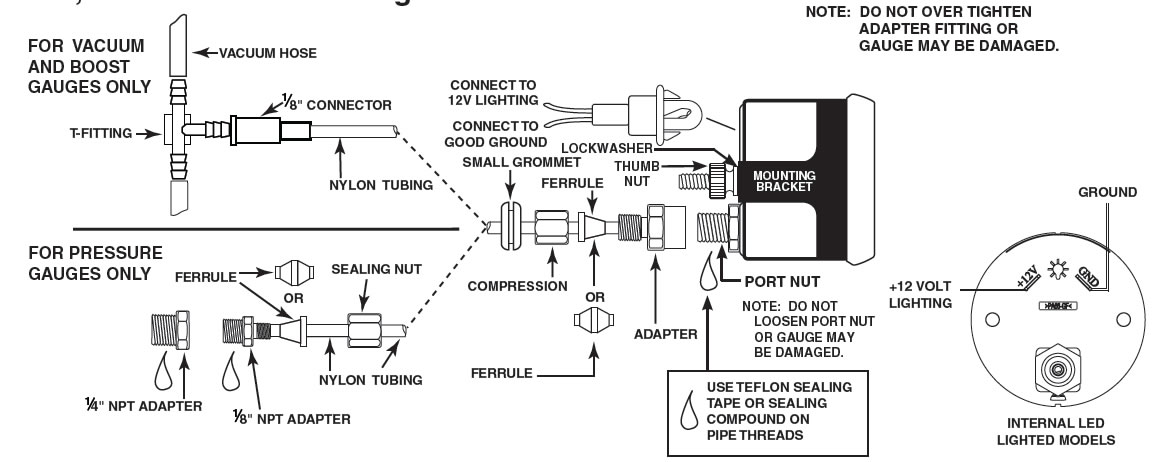
- Mechanical Gauges: These are the most common and generally more reliable. They use a physical connection – a vacuum hose – directly from the intake manifold to the gauge. The pressure in the manifold directly deflects a mechanism within the gauge, providing the reading.
- Electrical Gauges: These use a separate boost pressure sensor mounted in the engine bay, which converts the pressure into an electrical signal. This signal is then sent to the gauge to display the reading. Electrical gauges offer more flexibility in terms of placement and features, such as peak hold and warning alarms.
This guide will focus on the installation of electrical boost gauges, as they are becoming increasingly popular due to their advanced features and ease of routing compared to running a vacuum line through the firewall.
The Boost Pressure Sensor
The boost pressure sensor, also known as a manifold absolute pressure (MAP) sensor (though it's important to distinguish between the OEM MAP sensor and the aftermarket boost sensor, as they may have different ranges and outputs), is the heart of an electrical boost gauge setup. This sensor measures the absolute pressure in the intake manifold. Most aftermarket boost sensors output a voltage signal that corresponds to the pressure reading. The gauge interprets this voltage and displays the pressure accordingly. The sensor's range is critical; choose one appropriate for your vehicle's boost levels. A sensor with a 30 PSI range won't be very accurate if you're only running 5 PSI, and a sensor with a 15 PSI range won't work at all if you're running 20 PSI!
Tools and Materials
Here’s a list of the tools and materials you’ll likely need:
- Boost gauge kit (including gauge, sensor, wiring harness, and vacuum hose)
- Appropriate size vacuum hose (if the kit-supplied hose is insufficient or of poor quality)
- Wiring connectors (butt connectors, spade connectors, or solder and heat shrink tubing)
- Wire stripper/crimper
- Screwdrivers (Phillips and flathead)
- Socket set and wrench set
- Drill and drill bits (for mounting the gauge)
- Multimeter
- Zip ties
- Electrical tape
- Vacuum hose cutter or sharp knife
- Panel removal tools (optional, but helpful for interior work)
- Eye protection
- Gloves
Installation Steps
Follow these steps carefully for a successful boost gauge installation:
1. Gauge Placement and Mounting
First, decide where you want to mount the gauge. Common locations include the A-pillar, dashboard, or steering column. Consider visibility, ease of access, and aesthetics. Once you've chosen a location, carefully plan how you'll route the wiring and vacuum hose. Use a gauge pod for a clean and professional look.
Use a drill and appropriate-sized drill bit to create mounting holes in the chosen location, if necessary. Secure the gauge pod or mounting bracket. Carefully install the gauge into the pod or bracket.
2. Sensor Placement and Vacuum Line Connection
Next, find a suitable location to mount the boost pressure sensor. It should be in a cool, dry location, away from direct heat and vibration. Ideally, mount it as close as possible to the intake manifold to minimize delay in pressure readings. Consider using existing mounting points or brackets to avoid drilling new holes.
Now, connect the vacuum hose to the intake manifold. You'll need to find a vacuum source downstream of the throttle body. Many vehicles have unused vacuum ports that you can utilize. If not, you may need to use a T-fitting to tap into an existing vacuum line. Common lines to tap into include the fuel pressure regulator vacuum line or the brake booster line (exercise extreme caution when tapping into the brake booster line, as any leaks here will compromise braking performance!).
Important: Ensure the vacuum hose is securely connected to both the intake manifold and the boost pressure sensor. Use hose clamps or zip ties to prevent leaks. Leaks will result in inaccurate readings and potential engine performance issues.
3. Wiring the Sensor and Gauge
This is where things get a bit more technical. Refer to the wiring diagram provided with your boost gauge kit. Typically, the boost pressure sensor will have three wires:
- Power (typically +12V): Connect this wire to a switched +12V source. This means the power is only on when the ignition is on. Use a circuit tester to verify that the chosen wire is indeed a switched +12V source. You can tap into an existing wire using a T-tap connector or run a dedicated wire to the fuse box. Use an appropriate fuse for the gauge's power consumption.
- Ground: Connect this wire to a reliable ground point on the vehicle's chassis. A clean, unpainted metal surface is best. Scrape away any paint or rust to ensure a good connection.
- Signal Wire: This wire carries the voltage signal from the sensor to the gauge. Connect it to the corresponding signal wire on the gauge.
The gauge itself will also require power and ground. Connect these wires to the same switched +12V source and ground point as the sensor, or to a separate, dedicated power and ground source.
Pro Tip: Always use proper wiring connectors and insulation. Solder and heat shrink tubing provide the most reliable connections. Avoid using twist-on wire connectors (wire nuts) in automotive applications, as they are prone to loosening and causing electrical problems. Properly crimped butt connectors are an acceptable alternative.
4. Calibration and Testing
Once everything is wired up, it's time to test and calibrate the gauge. Turn on the ignition (without starting the engine). The gauge should power up and display a reading. At this point, the gauge should read approximately 0 PSI (atmospheric pressure). Some gauges may have a calibration setting to adjust the zero point. Refer to the gauge's instruction manual for specific calibration procedures.
Now, start the engine and let it idle. The gauge should show a slight vacuum reading (negative PSI). This indicates that the engine is creating vacuum in the intake manifold during idle. Rev the engine slightly. The gauge should respond by showing a decrease in vacuum or a slight increase in pressure.
Finally, take the vehicle for a test drive. Under acceleration, the gauge should display positive pressure (boost). Monitor the boost levels carefully and ensure they are within the expected range for your vehicle. If the gauge reads abnormally high or low, double-check all your connections and sensor placement. You might also need to consult with a professional tuner or mechanic to diagnose any underlying issues.
5. Final Touches
Once you're satisfied with the gauge's performance, tidy up the wiring and vacuum hose. Use zip ties to secure the wires and hose to prevent them from dangling or rubbing against other components. Double-check that all connections are secure. Reinstall any interior panels that were removed during the installation.
Troubleshooting
Here are some common issues you might encounter during boost gauge installation and how to troubleshoot them:
- Gauge not powering on: Check the fuse for the gauge's power source. Verify that the power and ground connections are secure. Use a multimeter to check for voltage at the gauge's power input.
- Inaccurate readings: Check for vacuum leaks in the hose connections. Ensure the boost pressure sensor is properly installed and connected. Verify that the sensor is compatible with the gauge. Calibrate the gauge according to the manufacturer's instructions.
- Gauge flickering or erratic readings: Check for loose wiring connections. Ensure the ground connection is clean and secure. Inspect the wiring for any damage or shorts.
- Boost gauge showing vacuum when it should be showing boost: Make sure the vacuum line is connected to a source after the throttle body. If it's connected before, it will only read vacuum.
Final Thoughts
Installing a boost gauge is a rewarding project that provides valuable information about your engine's performance. By following these steps carefully and paying attention to detail, you can successfully install a boost gauge and monitor your turbocharger's output with confidence. Remember to consult your vehicle's service manual and the gauge's instruction manual for specific details and recommendations. If you're unsure about any aspect of the installation, don't hesitate to seek professional assistance. Happy boosting!