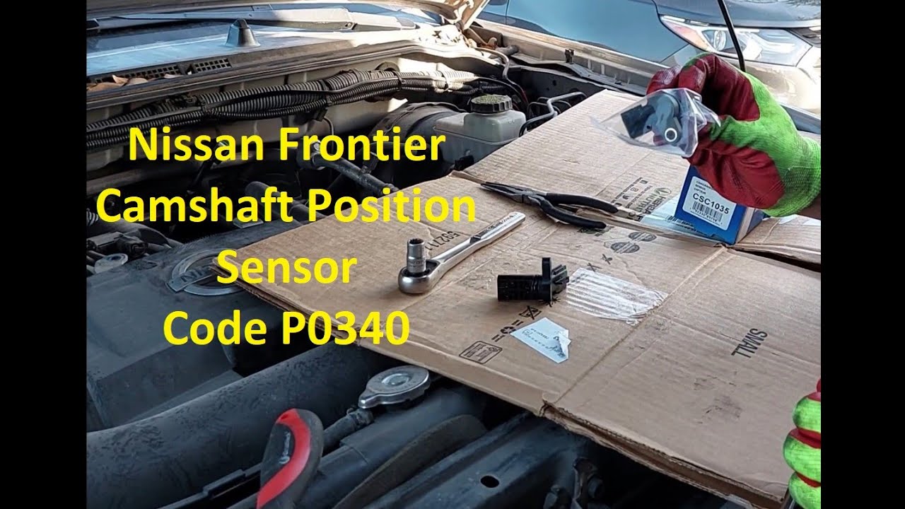
Camshaft Position Sensor Nissan Frontier
The Nissan Frontier, a stalwart of the compact/mid-size truck market, relies on a complex interplay of sensors and actuators to deliver optimal performance and fuel efficiency. Among these crucial components, the Camshaft Position Sensor (CMP) plays a vital, yet often overlooked, role. This guide aims to dissect the CMP sensor in the Nissan Frontier, exploring its function, operation, common failure modes, and troubleshooting techniques.
What is the Camshaft Position Sensor?
At its core, the CMP sensor's job is to inform the engine control unit (ECU) about the exact position of the camshaft(s). This information is critical for the ECU to precisely time fuel injection and ignition, ensuring efficient combustion and minimizing emissions. Without accurate camshaft position data, the engine may run poorly, misfire, or even refuse to start.
To understand its importance, consider the four-stroke engine cycle: intake, compression, power, and exhaust. The camshaft, driven by the timing chain or belt, controls the opening and closing of the intake and exhaust valves. Knowing the camshaft's rotational position allows the ECU to synchronize the fuel injectors, which deliver fuel into the cylinders, and the ignition system, which sparks the air-fuel mixture. Incorrect timing can lead to a cascade of problems, from reduced power and fuel economy to serious engine damage.
How the CMP Sensor Works: The Technical Details
The CMP sensor in most Nissan Frontiers is a Hall-effect sensor. This type of sensor utilizes the Hall effect, a phenomenon discovered by Edwin Hall in 1879, to detect the presence and strength of a magnetic field. Here's a breakdown of the working principle:
- The Target Wheel: A toothed or slotted wheel, known as a target wheel or reluctor ring, is attached to the camshaft. The teeth or slots create variations in the magnetic field as the camshaft rotates.
- The Hall-Effect Element: The sensor itself contains a small semiconductor material that carries a constant current.
- Magnetic Field Interaction: When a tooth of the target wheel passes near the Hall-effect element, it concentrates the magnetic field, causing a voltage to be generated across the semiconductor. When a slot passes, the magnetic field weakens, and the voltage decreases.
- Signal Processing: The sensor's internal circuitry interprets these voltage fluctuations as pulses. Each pulse represents a specific position of the camshaft.
- Data Transmission: The sensor sends these pulses as a digital signal to the ECU. The ECU analyzes the frequency and pattern of the pulses to determine the camshaft's angular position and speed.
The signal produced by the Hall-effect sensor is typically a square wave. The high voltage portion of the wave corresponds to the presence of a tooth, while the low voltage portion corresponds to the presence of a slot. The ECU measures the time between these transitions to determine the camshaft's speed and position with high precision.
Some older or less common CMP sensors might employ a variable reluctance (VR) sensor instead. VR sensors use a coil of wire wrapped around a magnet. As the target wheel rotates, the changing magnetic field induces a voltage in the coil. However, Hall-effect sensors are generally more accurate and reliable, especially at low engine speeds.
Why CMP Sensors Fail: Common Failure Modes
Like any electronic component subjected to the harsh environment of an engine bay, CMP sensors are prone to failure. Here are some of the most common causes:
- Heat Soak: Prolonged exposure to high temperatures can degrade the sensor's internal components, leading to inaccurate readings or complete failure.
- Vibration: Constant vibration can loosen connections, damage the sensor's housing, or cause the internal components to break down.
- Contamination: Oil leaks, coolant spills, or debris can contaminate the sensor, interfering with its ability to detect the magnetic field accurately.
- Wiring Problems: Damaged wiring, corroded connectors, or short circuits in the sensor's wiring harness can prevent the signal from reaching the ECU.
- Target Wheel Damage: A bent or damaged target wheel can produce erratic signals, leading to inaccurate camshaft position readings.
- Sensor Age: Over time, the sensor's internal components can simply wear out, resulting in decreased performance and eventual failure.
A failing CMP sensor can manifest in a variety of symptoms, often mimicking other engine problems. Accurate diagnosis is crucial to avoid unnecessary repairs.
Symptoms of a Failing CMP Sensor
Recognizing the symptoms of a failing CMP sensor is the first step in diagnosing the problem. Here are some common indicators:
- Check Engine Light (CEL): This is the most common symptom. The ECU will typically store diagnostic trouble codes (DTCs) related to the CMP sensor, such as P0340 (Camshaft Position Sensor Circuit Malfunction) or P0341 (Camshaft Position Sensor Circuit Range/Performance).
- Engine Misfires: Inaccurate camshaft timing can lead to misfires, resulting in rough idling, poor acceleration, and reduced fuel economy.
- Hard Starting or No Start: The ECU needs camshaft position information to properly time fuel injection and ignition. A faulty CMP sensor can prevent the engine from starting altogether.
- Stalling: The engine may stall unexpectedly, particularly at low speeds or when idling.
- Reduced Fuel Economy: Incorrect timing can lead to inefficient combustion, resulting in decreased fuel economy.
- Lack of Power: Inaccurate timing can reduce engine power and torque, especially at higher RPMs.
Troubleshooting and Testing the CMP Sensor
Diagnosing a CMP sensor issue requires a systematic approach. Here's a step-by-step guide:
- Read Diagnostic Trouble Codes (DTCs): Use an OBD-II scanner to retrieve any stored DTCs. Note the codes and their descriptions.
- Visual Inspection: Carefully inspect the CMP sensor and its wiring harness for any signs of damage, corrosion, or loose connections.
- Wiring Continuity Test: Use a multimeter to check the continuity of the wires connecting the sensor to the ECU. Refer to the vehicle's wiring diagram for the correct pin assignments.
- Voltage Test: With the ignition on, check for the presence of the correct voltage at the sensor's power supply wire. Consult the vehicle's service manual for the specified voltage range.
- Signal Test: Use an oscilloscope or a multimeter set to AC voltage to observe the sensor's signal output while the engine is running. The signal should be a square wave with a consistent frequency and amplitude. This requires a moderate level of experience and caution.
- Resistance Test: Some service manuals provide a resistance specification for the CMP sensor. Using a multimeter, measure the resistance across the sensor's terminals. If the reading is outside the specified range, the sensor is likely faulty. However, note that this test isn't always definitive for Hall-effect sensors.
- Component Substitution: If the above tests are inconclusive, consider temporarily replacing the CMP sensor with a known good sensor to see if the symptoms disappear.
Important Safety Note: When working on the electrical system, always disconnect the negative battery cable to prevent accidental short circuits and electrical shocks.
Replacement and Maintenance
If the CMP sensor is found to be faulty, it should be replaced with a new, high-quality sensor. When replacing the sensor, follow these guidelines:
- Use a Genuine or OEM-Equivalent Sensor: While aftermarket sensors are often cheaper, they may not meet the same quality standards as genuine or OEM-equivalent sensors. Using a lower-quality sensor can lead to premature failure and performance issues.
- Clean the Mounting Surface: Ensure that the sensor mounting surface is clean and free of debris before installing the new sensor.
- Torque to Specification: Tighten the sensor mounting bolts to the specified torque to prevent damage to the sensor or the engine.
- Reconnect the Wiring Harness: Ensure that the wiring harness connector is securely attached to the sensor.
- Clear Diagnostic Trouble Codes: After replacing the sensor, clear any stored DTCs using an OBD-II scanner.
Preventative maintenance can help extend the life of the CMP sensor. Regularly inspect the engine bay for oil leaks or coolant spills that could contaminate the sensor. Keep the wiring harness clean and free of corrosion. Address any engine problems promptly to prevent them from stressing the sensor.
Conclusion
The Camshaft Position Sensor is a small but critical component in the Nissan Frontier's engine management system. Understanding its function, operation, failure modes, and troubleshooting techniques empowers owners and enthusiasts to diagnose and resolve issues, ensuring optimal engine performance and longevity. By following the guidelines outlined in this guide, you can effectively maintain your Frontier's CMP sensor and keep your truck running smoothly for years to come.