Egi Pump Relay Circuit Analysis And Failure Diagnostics
Let's dive into the Electronic Gasoline Injection (EGI) pump relay circuit – a critical component for keeping your engine running smoothly. If your fuel pump isn't priming, or your engine stalls unexpectedly, the EGI relay circuit is a prime suspect. In this article, we'll break down how this circuit works, how to analyze it, and how to diagnose common failures. We'll assume you have some basic understanding of automotive electrical systems, including how to use a multimeter.
Understanding the EGI Pump Relay Circuit
The EGI pump relay circuit’s primary function is to safely and reliably supply power to the fuel pump. Think of it as a heavy-duty switch controlled by the Engine Control Unit (ECU), or sometimes, directly by the ignition switch. This controlled switch provides the necessary current to the fuel pump without overloading smaller circuits.
Components of the EGI Pump Relay Circuit
A typical EGI pump relay circuit will include the following key components:
- Battery: The source of power for the entire system.
- Ignition Switch: Signals the system to activate when the key is turned to the "ON" or "START" position.
- ECU (Engine Control Unit): The "brain" of the engine management system. It controls the fuel pump operation based on various sensor inputs.
- EGI Relay: An electromagnetic switch consisting of a coil and contacts. When the coil is energized, it closes the contacts, completing the circuit to the fuel pump.
- Fuel Pump: Draws fuel from the tank and delivers it to the fuel injectors at the required pressure.
- Inertia Switch (Fuel Cutoff Switch): A safety device designed to cut power to the fuel pump in the event of a collision. While not always present, it's a vital safety feature.
- Wiring and Connectors: The conduits that carry the electrical signals and power throughout the circuit.
- Fuses: Protective devices that blow (open the circuit) if the current exceeds a safe level.
How the Circuit Works - Step-by-Step
Let's walk through the typical operation of the EGI pump relay circuit:
- Initial Key Position (OFF): The circuit is de-energized. The relay contacts are open, and no power is supplied to the fuel pump.
- Key to ON Position: The ignition switch sends a signal to the ECU. Many ECUs are programmed to activate the EGI relay for a short duration (typically 1-3 seconds) to prime the fuel system. This priming action builds up fuel pressure before the engine starts. This is the sound you hear when you first turn the key and hear the fuel pump "whirring".
- ECU Control: The ECU provides a ground path to the EGI relay coil. When the coil is grounded (and has power from the ignition), it creates an electromagnetic field, pulling the relay contacts closed.
- Fuel Pump Activation: With the relay contacts closed, battery voltage is now supplied to the fuel pump, causing it to run.
- Engine Running: The ECU continues to monitor engine parameters (RPM, load, etc.) and maintains the ground signal to the EGI relay, keeping the fuel pump running. If the ECU detects a critical error (e.g., no engine RPM signal), it may cut power to the relay, shutting off the fuel pump as a safety measure.
- Key to START Position: During cranking, the ECU continues to control the relay to ensure continuous fuel supply for starting.
- Key to OFF Position: The ignition switch is turned off, the ECU de-energizes the EGI relay, the contacts open, and the fuel pump stops.
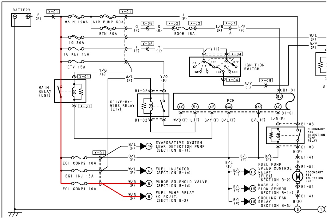
EGI Pump Relay Circuit Analysis: Reading Wiring Diagrams
Before you start probing wires, you need to understand the wiring diagram for your specific vehicle. These diagrams, typically found in a repair manual, show the layout of the circuit, including the location of components, wire colors, and connector pin numbers. Learning to read these diagrams is a crucial skill for any DIY mechanic.
Key things to look for in the diagram:
- Relay Location: Where is the EGI relay physically located in the vehicle (e.g., under the dash, in the engine bay fuse box)?
- Pin Assignments: Which pin on the relay corresponds to the coil power, coil ground, switched power input, and switched power output to the fuel pump? This information is essential for testing.
- Wire Colors: Use the wire colors in the diagram to identify specific wires in the vehicle.
- Fuse Locations: Identify the fuses that protect the EGI relay circuit and the fuel pump circuit.
- Ground Points: Locate the ground points for the ECU and the relay. A poor ground can cause all sorts of intermittent problems.
Failure Diagnostics: Troubleshooting Common Issues
Now, let's get to the heart of the matter: diagnosing problems in the EGI pump relay circuit. Here are some common failures and how to troubleshoot them:
No Fuel Pump Prime/No Fuel Pump Operation
This is the most common symptom. The engine cranks, but doesn't start, or it starts and immediately stalls.
- Check the Fuses: Start with the basics. Use a multimeter to test the fuel pump fuse and the EGI relay fuse. A visual inspection isn't always reliable, as a fuse can be cracked without being obvious. Ensure you are testing for continuity, not just looking at it.
- Check the Relay:
- Relay Test: Remove the relay and test it directly. You can use a 12V power supply and a multimeter. Connect the power supply to the relay coil terminals (refer to the wiring diagram for polarity). You should hear a "click" as the relay activates. Use the multimeter to check for continuity between the switched power input and output terminals when the relay is energized. If the relay doesn't click or doesn't pass the continuity test, replace it.
- Relay Socket Voltage: With the relay removed, use a multimeter to check for voltage at the relay socket terminals. With the ignition switch in the "ON" position, you should have 12V at the coil power terminal and at the switched power input terminal. If voltage is missing, trace the wiring back to the ignition switch and the battery, checking for broken wires or corroded connectors.
- Relay Socket Ground: With the relay removed, use a multimeter to verify that the coil ground terminal has a good connection to ground when the ECU should be activating the relay. This usually requires the key to be in the "ON" position or during cranking. You may need an assistant to help. If the ground is missing, trace the wiring back to the ECU, checking for broken wires or a faulty ECU.
- Check the Inertia Switch (if equipped): Locate the inertia switch (usually in the trunk or near the driver's side footwell). Press the reset button to ensure it's not tripped. Use a multimeter to check for continuity through the switch.
- Check the Fuel Pump Wiring: Disconnect the fuel pump connector (usually located near the fuel tank). Use a multimeter to check for voltage at the fuel pump connector when the EGI relay should be energized. If voltage is present, the problem is likely with the fuel pump itself. If voltage is missing, trace the wiring back to the EGI relay, checking for broken wires or corroded connectors. Also, verify the ground connection to the fuel pump is solid.
- ECU Issues: In rare cases, the ECU may be faulty and not providing the ground signal to the EGI relay. This is usually diagnosed by ruling out all other possibilities. You may need a professional scan tool to check the ECU's output signals.
Intermittent Fuel Pump Operation
The engine runs fine sometimes, but stalls unexpectedly at other times. This can be a tricky problem to diagnose.
- Check for Loose Connections: Carefully inspect all connectors in the EGI pump relay circuit, paying close attention to the relay socket, the fuel pump connector, and the ECU connectors. Look for corroded terminals or loose pins. Clean and reseat the connectors.
- Check for Wiring Issues: Inspect the wiring harness for any signs of damage, such as chafing, cuts, or exposed wires. Pay particular attention to areas where the wiring harness is routed near sharp edges or hot engine components.
- Check the Ground Connections: As mentioned before, a poor ground can cause intermittent problems. Clean and tighten all ground connections associated with the ECU, the EGI relay, and the fuel pump.
- Monitor Relay Voltage: If possible, connect a voltmeter to the EGI relay coil terminals and monitor the voltage while driving the vehicle. If the voltage drops out when the engine stalls, it indicates a problem with the ignition switch, the ECU, or the wiring to the relay.
- Heat Sensitivity: Sometimes, components fail only when they get hot. Try using a heat gun (cautiously!) to heat up components like the relay or ECU to see if you can induce the fault. Be very careful not to damage anything with excessive heat.
Voltage Drop Testing
Voltage drop testing is a powerful technique for identifying resistance in a circuit. It's particularly useful for diagnosing problems with wiring and connectors.
How it works: When current flows through a circuit, any resistance in the circuit will cause a voltage drop. By measuring the voltage drop across different sections of the circuit, you can pinpoint areas with excessive resistance.
Performing a Voltage Drop Test:
- Connect the Voltmeter: Connect the positive lead of the voltmeter to one end of the circuit section you want to test and the negative lead to the other end.
- Apply a Load: With the circuit energized and under load (e.g., the fuel pump running), measure the voltage drop.
- Interpret the Results: A voltage drop of more than 0.5V typically indicates excessive resistance. Investigate the wiring, connectors, and ground connections in that section of the circuit.
Example: To test the voltage drop across the positive wire to the fuel pump, connect the voltmeter between the fuel pump positive terminal and the output terminal of the EGI relay. If you measure a voltage drop of more than 0.5V, there is likely a problem with the wiring or connectors between the relay and the fuel pump.
Final Thoughts
Diagnosing electrical problems can be challenging, but with a systematic approach and a good understanding of the circuit, you can often track down the culprit. Remember to always refer to the wiring diagram for your specific vehicle and to take your time. If you're not comfortable working with electrical systems, it's best to consult a qualified mechanic. Good luck, and happy wrenching!
Disclaimer: This article is for informational purposes only and should not be considered a substitute for professional advice. Always consult a qualified mechanic for any automotive repairs or maintenance.