Fuse Box Circuit Mapping And Current Capacity Analysis
Alright, let's talk about fuse boxes. They're the unsung heroes of your car's electrical system, protecting everything from your headlights to your engine control unit (ECU) from potentially damaging electrical overloads. Understanding your fuse box – specifically circuit mapping and current capacity analysis – is crucial for anyone doing electrical modifications, troubleshooting issues, or simply wanting to better understand their vehicle.
What is a Fuse and Why Do We Care?
Before diving deep, let's cover the basics. A fuse is a safety device designed to protect an electrical circuit from excessive current. It contains a thin wire or metal strip that melts and breaks the circuit if the current exceeds its rated amperage. Think of it like a dam – it holds back the flow until it reaches a certain point, then it intentionally breaks to prevent further damage downstream.
Fuses are rated in amperes (amps), which is a unit of measure for electrical current. Common automotive fuse ratings range from 5A to 40A. The higher the amperage rating, the more current the fuse can handle before blowing. Using the wrong amperage fuse can be dangerous – too low and it will constantly blow, too high and it might not protect the circuit adequately, potentially leading to fires or damage to expensive components.
Fuse Box Circuit Mapping: The Key to Understanding
Circuit mapping refers to identifying which electrical components are protected by each individual fuse in your fuse box. This is essential for diagnosing electrical problems and planning any modifications. Without a map, you're essentially poking around in the dark, hoping you don't accidentally short something out or damage a critical system.
Here's how to create a fuse box circuit map:
1. Locate Your Fuse Box(es)
Most vehicles have at least two fuse boxes: one under the dashboard (usually on the driver's side) and another in the engine compartment. Some vehicles, especially larger SUVs and trucks, may have additional fuse boxes in the cargo area or under the hood. Consult your owner's manual to find the locations of all fuse boxes in your vehicle. The manual is also the place to start when finding the factory circuit mappings.
2. Obtain the Fuse Box Diagram
Inside the fuse box cover, you should find a diagram that identifies each fuse. This diagram may be printed on the underside of the cover itself, or it may be a separate piece of paper tucked inside. If the diagram is missing or illegible, you can usually find a replacement online (search for "[your car's year, make, and model] fuse box diagram"). Pay close attention to the diagram's orientation – it's easy to misread if you're looking at it upside down or sideways.
3. Decipher the Diagram (and Verify!)
The diagram will show the position of each fuse and list the component or circuit it protects. For example, it might say "Headlights," "Fuel Pump," "ECU," "ABS," or "Cigar Lighter." These descriptions can sometimes be vague, so it's important to verify the function of each fuse. This is where a multimeter and a bit of detective work come in handy.
4. Verifying Fuse Function with a Multimeter
A multimeter is an invaluable tool for any automotive electrical work. Here's how to use it to verify fuse function:
Continuity Test: Set your multimeter to the continuity setting (often indicated by a diode symbol or a sound wave symbol). Remove the fuse and touch the multimeter probes to each of the fuse's terminals. If the fuse is good, the multimeter will beep or display a low resistance value (close to 0 ohms). If the fuse is blown, the multimeter will show an open circuit (infinite resistance or no continuity).
Now, let's say you want to confirm that a specific fuse protects the radio. Remove the fuse, turn on the radio, and see if it still works. If the radio goes dead, you've confirmed that the fuse protects the radio. Important: Always replace the fuse immediately after testing to ensure the circuit is protected.
5. Create Your Own Detailed Map
While the factory diagram is a good starting point, it's often helpful to create your own, more detailed map. This is especially useful if you've made modifications to your vehicle's electrical system. Use a notebook or a spreadsheet to record the position, amperage rating, and a detailed description of what each fuse protects. For example, instead of just "Headlights," you might write "Low Beam Headlights (Left and Right)." Note any aftermarket modifications tied into specific circuits.
Current Capacity Analysis: Ensuring Safe Electrical Modifications
Current capacity analysis is the process of determining how much current a particular circuit can safely handle. This is critical when you're adding new electrical components to your vehicle, such as aftermarket lights, audio systems, or performance modifications. Overloading a circuit can lead to blown fuses, damaged wiring, and even fires.
Understanding Circuit Load
Every electrical component draws a certain amount of current. This current draw is typically measured in amps (A). The total current draw of a circuit is the sum of the current draw of all the components connected to that circuit.
For example, let's say you have a circuit that protects the following:
- Headlights: 5A each (10A total)
- Parking Lights: 1A each (2A total)
- Taillights: 1A each (2A total)
The total current draw of this circuit is 10A + 2A + 2A = 14A.
Determining the Maximum Safe Current
The maximum safe current for a circuit is determined by several factors, including the fuse rating, the wire gauge (thickness), and the connectors used in the circuit.
Fuse Rating: The fuse rating is the most obvious limitation. You should never exceed the fuse rating for a circuit. Doing so will cause the fuse to blow repeatedly, and it could also damage the wiring or components.
Wire Gauge: The wire gauge is a measure of the wire's thickness. Thicker wires can carry more current than thinner wires. Automotive wiring is typically measured in AWG (American Wire Gauge). A lower AWG number indicates a thicker wire (e.g., 12 AWG is thicker than 16 AWG). You can find online charts that specify the safe current carrying capacity for different wire gauges. Remember to factor in the length of the wire run, as longer runs experience more voltage drop and heat, further reducing capacity.
Connectors: Connectors can also limit the current capacity of a circuit. Make sure to use high-quality connectors that are rated for the appropriate current level. Poorly crimped or undersized connectors can create resistance, causing heat and potentially leading to failure.
Calculating Total Circuit Load and Assessing Capacity
1. Identify the circuit you want to modify. Use your circuit map to determine which fuse protects the circuit you're interested in.
2. Determine the current draw of the existing components on the circuit. You can usually find the current draw information in the component's specifications or on a label on the component itself. If you can't find the information, you can use a multimeter to measure the current draw.
3. Determine the current draw of the new component you want to add. Again, you can usually find this information in the component's specifications or on a label. If you can't find the information, you can use a multimeter to measure the current draw.
4. Calculate the total current draw of the circuit. Add the current draw of all the existing components to the current draw of the new component.
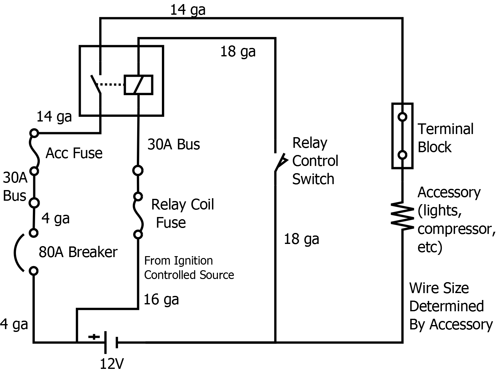
5. Compare the total current draw to the fuse rating and wire gauge capacity. If the total current draw exceeds the fuse rating or the wire gauge capacity, you'll need to take steps to reduce the current draw or use a different circuit. Consider using a relay to power the new component directly from the battery, using the existing circuit only as a trigger signal. This isolates the high current draw of the new component from the existing circuit.
Best Practices for Electrical Modifications
- Always use the correct fuse rating. Never replace a fuse with a higher amperage fuse unless you've upgraded the wiring and connectors to handle the increased current.
- Use high-quality wiring and connectors. Cheap wiring and connectors can cause problems down the road.
- Properly crimp and insulate all connections. Poorly crimped connections can create resistance, causing heat and potentially leading to failure.
- Use a wiring diagram. A wiring diagram will help you understand how the circuit is wired and ensure that you're making the correct connections.
- Test your work thoroughly. After making any electrical modifications, test the circuit to make sure it's working properly.
By understanding fuse box circuit mapping and current capacity analysis, you can safely and effectively modify your vehicle's electrical system. Always prioritize safety and take your time to do the job right. If you're unsure about any aspect of the process, consult a qualified automotive electrician.