How To Remote Start Nissan Maxima
So, you're looking to delve into the fascinating world of remote starting your Nissan Maxima? Excellent! This guide provides a comprehensive overview of the remote start system, specifically targeting the electrical aspects. We'll break down the key components, explain how it all works, and give you some practical troubleshooting tips. Understanding this system is invaluable for repairs, modifications, or simply satisfying your curiosity about how your car operates.
Key Specs and Main Parts
Before we dive into the nitty-gritty, let's establish some common ground regarding the core elements involved. The remote start system in a Maxima, typically found in models from the late 2000s onwards, consists of several interconnected components. Keep in mind that the exact components and their integration can vary slightly depending on the model year and trim level. However, the fundamental principles remain consistent.
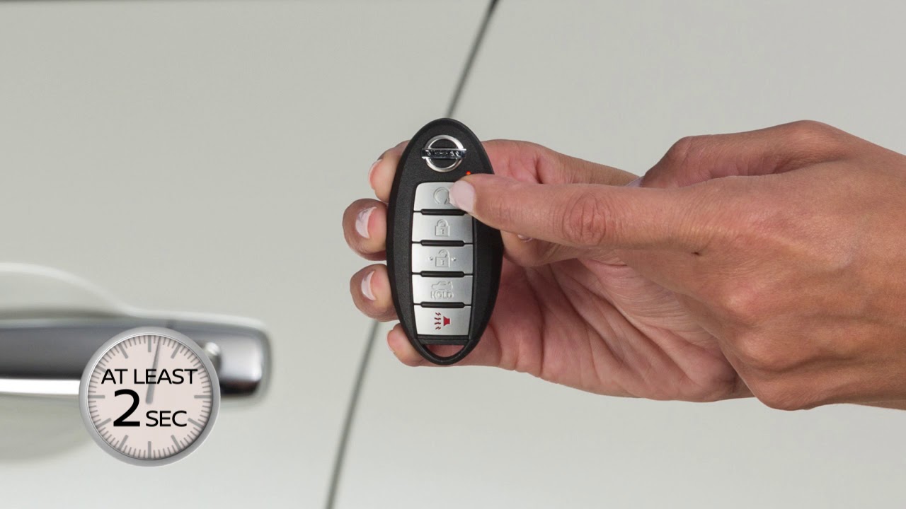
- Remote Start Transmitter (Key Fob): This is your handheld device for initiating the remote start sequence. It transmits a radio frequency (RF) signal to the vehicle.
- Remote Start Receiver Module: This module, usually located within the vehicle's cabin (often near the Body Control Module or BCM), receives the RF signal from the key fob and decodes the instructions.
- Hood Switch: A critical safety feature. This switch prevents remote starting if the hood is open, ensuring that no one accidentally starts the engine while someone is working under the hood. It's typically a simple normally-closed switch that opens when the hood is raised.
- Brake Pedal Switch: Another crucial safety component. The brake pedal must *not* be depressed during the remote start sequence. The brake pedal switch provides this verification.
- Body Control Module (BCM): This is the central processing unit for many of the vehicle's electrical functions, including security, lighting, and, in many cases, remote start. The remote start receiver module often interfaces directly with the BCM.
- Ignition System Wiring: These are the wires that connect the remote start system to the vehicle's ignition system. They are responsible for energizing the appropriate circuits to start the engine. Expect to see connections related to the starter solenoid, ignition power, and accessory power.
- Neutral Safety Switch (Automatic Transmission Only): Ensures the vehicle is in Park or Neutral before allowing the remote start to engage. A safety interlock to prevent unintended movement.
- Immobilizer Bypass Module (If Applicable): Some models have an immobilizer system that prevents the engine from starting without the correct key present. In this case, a bypass module temporarily circumvents the immobilizer during the remote start sequence. This might involve cloning the key's transponder signal or temporarily disabling the immobilizer.
Symbols – Understanding the Wiring Diagram
Interpreting a wiring diagram is key to understanding the remote start system. Here's a breakdown of common symbols and conventions:
- Lines: Solid lines represent wires. Dashed lines often indicate shielded cables or signal paths. The thickness of the line doesn't necessarily correspond to wire gauge, but thicker lines may be used for higher current circuits.
- Colors: Wire colors are usually indicated by abbreviations (e.g., BLK for black, RED for red, BLU for blue, GRN for green, YEL for yellow, WHT for white). Sometimes, a stripe color is also indicated (e.g., BLK/WHT for a black wire with a white stripe).
- Connectors: Connectors are represented by various symbols, often rectangles or circles with numbered pins. The diagram will usually provide a connector identification number, allowing you to locate the physical connector in the vehicle.
- Grounds: Ground symbols typically resemble an upside-down triangle or a series of horizontal lines decreasing in length.
- Fuses and Relays: Fuses are typically represented by a zigzag line within a rectangular box. Relays are shown as a coil (electromagnet) and a set of contacts (switch).
- Switches: Switches are illustrated showing the movable contact and the stationary contact(s). The position of the movable contact indicates the switch's current state (open or closed).
- ECUs/Modules: Electronic Control Units (ECUs) or modules (like the BCM) are often represented by a rectangle with labeled input and output connections.
Example: A solid red line connecting the battery positive terminal to a fuse, then to the ignition switch, indicates a direct power supply line. A dashed blue line connecting the remote start receiver to the BCM might represent a data communication signal.
How It Works
The remote start system's operation is a carefully orchestrated sequence of events:
- Signal Transmission: You press the remote start button on the key fob. The fob transmits an RF signal containing a unique code to the remote start receiver module in the car.
- Signal Reception and Verification: The receiver module receives the signal and verifies that it's a valid code. This is a security measure to prevent unauthorized starting.
- Safety Checks: The receiver module then checks the safety interlocks: is the hood closed (hood switch)? Is the brake pedal not pressed (brake pedal switch)? Is the transmission in Park or Neutral (neutral safety switch)?
- BCM Interaction: The receiver module sends a signal to the BCM indicating that a valid remote start request has been received and the safety checks have passed.
- Ignition Sequence: The BCM activates the appropriate circuits in the ignition system, mimicking the process of turning the key in the ignition. This typically involves energizing the ignition power, accessory power, and starter solenoid circuits in the correct sequence.
- Engine Start: The starter motor engages and cranks the engine until it starts.
- Run Time and Shutdown: Once the engine is running, the remote start system typically allows it to run for a pre-programmed amount of time (e.g., 10 or 15 minutes). If any of the safety interlocks are violated during this run time (e.g., the brake pedal is pressed), the engine will shut down.
Immobilizer Bypass (if applicable): If the vehicle has an immobilizer system, the immobilizer bypass module will be activated during the ignition sequence. It temporarily disables or circumvents the immobilizer to allow the engine to start.
Real-World Use – Basic Troubleshooting Tips
So, your remote start isn't working? Here are a few things to check:
- Key Fob Battery: This is the most common culprit. Replace the battery in your key fob.
- Hood Switch: Make sure the hood is fully closed. The hood switch can sometimes become misaligned or corroded. Inspect the switch and its wiring. You can temporarily bypass the switch for testing purposes only by disconnecting the wires and connecting them together (but remember to reconnect it afterwards for safety!).
- Blown Fuse: Check the fuses associated with the remote start system and the ignition system. Consult your owner's manual or a wiring diagram to identify the correct fuses.
- Faulty Brake Pedal Switch: If the brake pedal switch is malfunctioning and indicating that the brake pedal is pressed when it's not, the remote start will not work. Test the switch with a multimeter.
- BCM Issues: Problems with the BCM can be more complex to diagnose. If you suspect a BCM issue, it's best to consult a qualified technician.
- Receiver Module: A failing receiver module will prevent the remote start from working. This will often show up as not responding to the fob at all.
Tip: Start by visually inspecting all the wiring and connectors associated with the remote start system for any signs of damage, corrosion, or loose connections.
Safety – Risky Components
Working with automotive electrical systems involves inherent risks. Here are some key safety precautions:
- Disconnect the Battery: Always disconnect the negative battery terminal before working on any electrical components. This prevents accidental shorts and potential electrical shocks.
- Airbags: Be extremely careful when working near airbag modules or wiring. Accidental deployment of an airbag can cause serious injury. Consult the service manual for specific instructions on disabling the airbag system.
- High-Current Circuits: The ignition system and starter circuit involve high currents. Use appropriately rated tools and wiring.
- Fuel System: Be aware of the proximity of fuel lines and components. Avoid creating sparks or using open flames near the fuel system.
- Proper Grounding: Ensure all ground connections are clean and secure. Poor grounding can cause electrical problems and potentially damage components.
Important: If you're not comfortable working with automotive electrical systems, it's best to leave the work to a qualified technician. Incorrect wiring or modifications can damage your vehicle's electrical system and potentially create a fire hazard.
Understanding how the remote start system works in your Nissan Maxima gives you insight into the complex interactions of its components. Remember, safety first! And for those looking for more in-depth information, we have access to the full detailed wiring diagram specifically for your car. Please reach out, and we'll gladly provide it.