Intercooler Piping Routing And Pressure Drop Analysis
Turbocharging and supercharging have become increasingly prevalent methods for enhancing engine performance. A key component in these forced induction systems, particularly turbocharging, is the intercooler. Its primary function is to cool the compressed intake air before it enters the engine, increasing its density and allowing for more efficient combustion. However, the effectiveness of an intercooler hinges not only on its core design but also on the piping that connects it to the turbocharger and the intake manifold. Poor intercooler piping design can lead to significant pressure drops, negating many of the benefits of the intercooler itself. This article will delve into the intricacies of intercooler piping routing and pressure drop analysis, providing a comprehensive guide for optimizing your forced induction system.
Understanding the Basics: Pressure, Temperature, and Density
Before diving into routing and pressure drop, it's crucial to understand the fundamental relationships between pressure, temperature, and density in a gas. According to the Ideal Gas Law (PV=nRT), pressure (P) is directly proportional to density and temperature. When a turbocharger compresses air, it increases both its pressure and temperature. While increased pressure is desirable, the accompanying temperature rise reduces the air's density, hindering performance. This is where the intercooler steps in, cooling the air and increasing its density for a given pressure. Ideally, we want minimal pressure loss through the intercooler system while maximizing temperature reduction.
Factors Affecting Intercooler Piping Pressure Drop
Several factors contribute to pressure drop within the intercooler piping system. These can be broadly categorized as follows:
- Piping Length: Longer piping inherently leads to greater pressure drop due to increased frictional resistance against the pipe walls. This is a fundamental principle of fluid dynamics.
- Piping Diameter: Undersized piping restricts airflow, creating a significant bottleneck and resulting in high pressure drop. Conversely, excessively large piping can reduce air velocity, potentially decreasing intercooler efficiency.
- Bend Radius and Number of Bends: Each bend in the piping disrupts airflow, creating turbulence and increasing pressure drop. Sharp bends are particularly detrimental. The radius of the bend significantly impacts the amount of turbulence.
- Piping Material and Surface Roughness: Rougher internal surfaces increase frictional resistance, contributing to pressure drop. Smooth, polished surfaces are preferred.
- Coupler Design and Placement: Couplers, especially those with internal lips or misaligned edges, can introduce turbulence and pressure drop. Their placement near bends can exacerbate these effects.
- Intercooler Core Design: The internal design of the intercooler core itself will create a pressure drop. This is generally considered unavoidable and must be weighed against cooling performance.
Optimal Intercooler Piping Routing Strategies
The goal of intercooler piping routing is to minimize pressure drop while maintaining adequate airflow and structural integrity. Here are some key strategies:
- Minimize Piping Length: Route the piping as directly as possible between the turbocharger outlet, intercooler inlet, intercooler outlet, and intake manifold. Avoid unnecessary loops or detours.
- Use Smooth, Gradual Bends: Employ mandrel-bent piping with large bend radii to minimize turbulence and pressure drop. A general rule of thumb is to use a bend radius that is at least 1.5 times the pipe diameter. Avoid sharp 90-degree bends whenever possible.
- Choose the Correct Piping Diameter: Select a piping diameter that is appropriate for the engine's airflow requirements and the turbocharger's output. A common starting point is to match the diameter of the turbocharger outlet. Larger diameter is often better to a point but can increase weight and space constraints.
- Utilize Smooth Couplers: Use high-quality couplers with smooth internal surfaces and secure clamps to prevent leaks and minimize turbulence. Ensure that the couplers are properly aligned to avoid creating steps or lips in the airflow path. Avoid worm-gear clamps which can cut into the hose and fail, prefer constant tension clamps.
- Consider Piping Material: Aluminum is a popular choice due to its lightweight and excellent heat dissipation properties. Stainless steel offers greater strength and corrosion resistance but is heavier and less effective at dissipating heat. Silicone couplers offer good flexibility and heat resistance.
- Think About Heat Soak: Try to avoid routing the intercooler pipes too close to heat sources, such as the exhaust manifold. This can increase the temperature of the air and reduce the effectiveness of the intercooler.
Example Routing Scenarios:
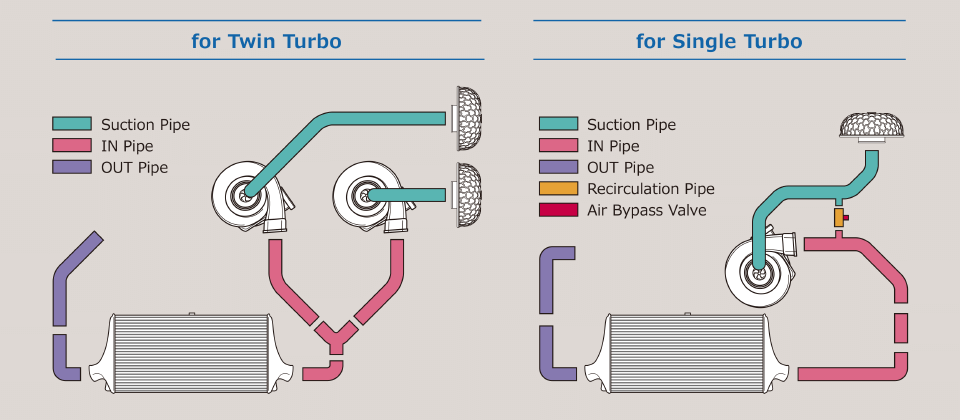
Consider a front-mount intercooler (FMIC) setup. A common routing strategy is to have the turbo outlet pipe run horizontally to the intercooler inlet on one side, then exit the intercooler on the opposite side and route the charge pipe up and over the engine bay to the throttle body. For a side-mount intercooler (SMIC), the routing is typically shorter, but space constraints often dictate more complex bends.
Pressure Drop Analysis Techniques
Quantifying pressure drop is essential for evaluating the effectiveness of the intercooler piping design. Several methods can be employed:
- Pressure Transducer Measurement: This is the most direct and accurate method. Install pressure transducers at the turbocharger outlet, intercooler inlet, intercooler outlet, and intake manifold. Log the pressure readings under various operating conditions (e.g., different engine speeds and boost levels). Calculate the pressure drop across each component (e.g., intercooler, piping). The difference between the turbo outlet and intake manifold pressure is the total system pressure drop. Aim for less than 2 PSI drop overall.
- Computational Fluid Dynamics (CFD) Simulation: CFD software can simulate airflow through the intercooler piping system, providing detailed information about pressure distribution, velocity profiles, and turbulence. This allows you to identify areas of high pressure drop and optimize the design accordingly. CFD requires specialized knowledge and software.
- Simplified Calculations (Estimations): While less precise, simplified calculations can provide a rough estimate of pressure drop. These calculations typically involve using empirical formulas and friction factors to estimate pressure loss based on pipe length, diameter, bend radius, and flow rate. Online calculators are also available. These should only be used as a starting point.
Analyzing Pressure Transducer Data:
When analyzing pressure transducer data, pay close attention to the pressure drop under peak boost conditions. A significant pressure drop at high boost indicates a restriction in the system. Compare pressure readings at different locations to pinpoint the source of the restriction. For example, if the pressure drop across the intercooler itself is high, it may indicate a clogged or undersized core. If the pressure drop is concentrated in a specific section of piping, it may indicate a sharp bend or undersized pipe.
Interpreting Results and Making Adjustments
Once you have collected pressure drop data, it's crucial to interpret the results and make adjustments to the intercooler piping design. If the pressure drop is excessive, consider the following:
- Increase Piping Diameter: If the piping diameter is too small, increase it to reduce flow restriction.
- Reduce Piping Length: Shorten the piping runs whenever possible.
- Replace Sharp Bends with Sweeping Bends: Replace sharp bends with mandrel-bent piping that has larger bend radii.
- Improve Coupler Design: Replace couplers with smooth, internally stepped couplers. Ensure they are properly aligned.
- Optimize Intercooler Core: Consider using a higher-flow intercooler core or modifying the existing core to reduce pressure drop. (This might impact cooling efficiency though)
- Smooth Internal Surfaces: Polish the inside of the pipes to reduce friction.
Iteratively test and refine the design until the pressure drop is minimized while maintaining adequate airflow and cooling efficiency. Always prioritize safety and reliability when making modifications to the intercooler piping system.
Remember, optimizing intercooler piping is a balancing act. You're trying to minimize pressure drop while maximizing cooling efficiency, within the constraints of available space and budget. A well-designed intercooler system can significantly improve engine performance and reliability.
By understanding the principles of intercooler piping routing and pressure drop analysis, you can optimize your forced induction system for maximum performance and efficiency. Careful planning, precise execution, and thorough testing are key to achieving the best possible results.