Radio Wiring Harness Pinout And Electrical Specifications
Understanding the intricacies of a car radio wiring harness is akin to deciphering the nervous system of your vehicle's audio entertainment. It's a complex web of wires, each meticulously assigned a specific task, working in harmony to deliver your favorite tunes, podcasts, and audiobooks. This guide delves into the pinout and electrical specifications of a typical radio wiring harness, providing an analytical and educational overview for curious readers and amateur engineers.
The Radio Wiring Harness: An Overview
The radio wiring harness serves as the critical interface between the head unit (the radio itself) and the vehicle's electrical system. It's essentially a standardized connector that carries power, ground, speaker outputs, and other control signals. The standardization aims to simplify radio replacement and upgrades, allowing installers to connect aftermarket head units without extensive modifications to the vehicle's original wiring. However, standardization isn't absolute; variations exist across different vehicle manufacturers, models, and years.
Decoding the Pinout: A Wire-by-Wire Examination
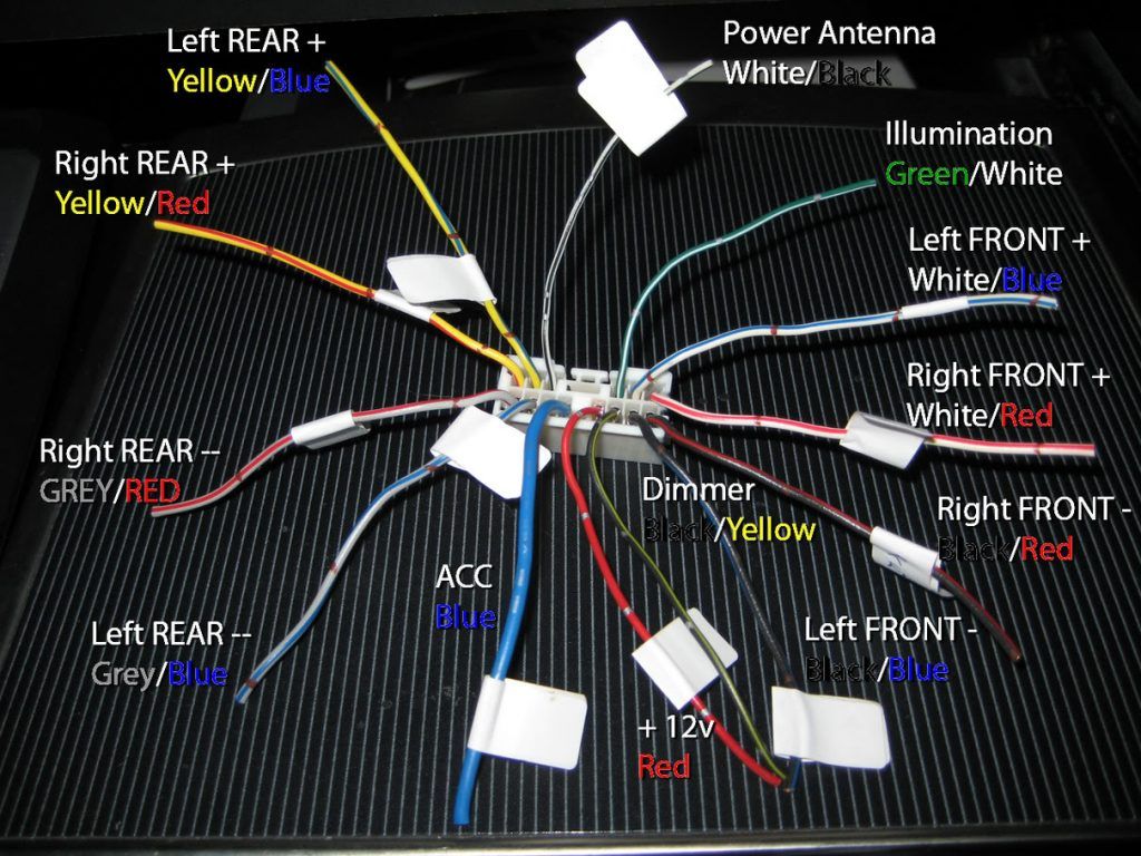
The pinout refers to the specific arrangement and function of each pin (or wire) within the connector. A typical car radio wiring harness will include the following categories of wires:
- Power Wires: These supply the necessary electrical energy to operate the head unit.
- Ground Wires: These provide the return path for the electrical current.
- Speaker Wires: These carry the amplified audio signal from the head unit to the speakers.
- Accessory Wires: These provide signals for features like remote turn-on for amplifiers, antenna control, and illumination.
- Data Wires (CAN Bus): In modern vehicles, these wires transmit digital data for various functions.
Let's examine each of these categories in more detail:
Power Wires
The power section typically includes two main wires:
- +12V Constant (Battery): This wire is connected directly to the vehicle's battery and provides a constant source of power to the head unit, even when the ignition is off. This is crucial for maintaining the radio's memory (station presets, settings, etc.). This wire is usually thicker than other wires and is often colored yellow.
- +12V Switched (Ignition/Accessory): This wire receives power only when the ignition is switched to the "Accessory" or "On" position. It signals the head unit to power on. This wire is commonly red.
Ground Wires
Ground wires are essential for completing the electrical circuit. A poor ground connection can lead to various issues, including weak audio, distortion, and even damage to the head unit.
- Chassis Ground: This wire is connected to the vehicle's chassis, providing a direct path to ground. It's typically black.
Speaker Wires
The speaker wires carry the amplified audio signal from the head unit to the speakers. Each speaker requires two wires: a positive (+) and a negative (-) wire. The colors of these wires are often standardized, but it's always best to double-check the wiring diagram for your specific vehicle.
Common speaker wire color pairings:
- Front Left: White (+) / White with Black Stripe (-)
- Front Right: Grey (+) / Grey with Black Stripe (-)
- Rear Left: Green (+) / Green with Black Stripe (-)
- Rear Right: Violet (+) / Violet with Black Stripe (-)
Accessory Wires
Accessory wires provide control signals for various features:
- Remote Turn-On (Amplifier): This wire provides a +12V signal when the head unit is powered on, signaling an external amplifier to turn on. It's typically blue.
- Antenna Control: This wire provides a +12V signal to raise or lower the vehicle's antenna when the radio is turned on. This is also commonly blue (often with a white stripe).
- Illumination: This wire is connected to the vehicle's headlight circuit and dims the head unit's display when the headlights are turned on. This is usually orange or orange with a white stripe.
- Reverse Signal: This wire is connected to the vehicle's reverse light circuit and signals the head unit (if equipped) to display the rearview camera image when the vehicle is in reverse. This is usually a violet/purple wire.
- Parking Brake Signal: This wire is connected to the parking brake switch. Some head units require this wire to be grounded to allow certain functions, such as video playback, to operate only when the parking brake is engaged.
Data Wires (CAN Bus)
In modern vehicles, the CAN (Controller Area Network) bus transmits digital data between various electronic control units (ECUs), including the head unit. These wires allow the head unit to communicate with the vehicle's other systems, such as the steering wheel controls, climate control, and vehicle information display.
CAN bus wires are typically twisted pairs and are often colored green and white or brown and yellow. It is crucial to avoid cutting or splicing these wires unless you are absolutely certain of their function and have the necessary knowledge and tools. Improper handling of CAN bus wires can disrupt the vehicle's electronic systems.
Electrical Specifications
Understanding the electrical specifications of the radio wiring harness is crucial for ensuring proper operation and preventing damage to the head unit or the vehicle's electrical system.
- Voltage: Most car radios operate on a 12V DC system. However, the actual voltage can fluctuate depending on the vehicle's charging system. It's important to ensure that the head unit is designed to operate within this voltage range.
- Current: The current draw of the head unit will vary depending on its features and power output. High-power amplifiers can draw a significant amount of current. It's essential to ensure that the vehicle's wiring harness and fuse are capable of handling the current draw of the head unit. Overloading the circuit can cause the fuse to blow or, in severe cases, damage the wiring.
- Impedance: The impedance of the speakers must match the output impedance of the head unit's amplifier. Mismatched impedance can lead to distortion, reduced power output, and even damage to the amplifier. Most car radios are designed to work with 4-ohm speakers.
- Power Output: The power output of the head unit is measured in watts. This indicates the amount of power the amplifier can deliver to the speakers. Higher power output typically results in louder and clearer audio.
Tools and Techniques for Working with Radio Wiring Harnesses
Working with radio wiring harnesses requires the right tools and techniques:
- Wiring Diagram: The most important tool is a wiring diagram for your specific vehicle. This will show the pinout of the radio wiring harness and the function of each wire.
- Wire Strippers: Use wire strippers to remove the insulation from the wires without damaging the conductors.
- Crimping Tool: Use a crimping tool to securely attach connectors and terminals to the wires.
- Multimeter: Use a multimeter to test the voltage and continuity of the wires.
- Heat Shrink Tubing: Use heat shrink tubing to insulate and protect the wire connections.
- Soldering Iron (Optional): Soldering the connections can provide a more secure and reliable connection, but it's not always necessary.
Safety Precautions
When working with electrical wiring, it's crucial to take the necessary safety precautions:
- Disconnect the Battery: Always disconnect the vehicle's battery before working on the electrical system. This will prevent accidental short circuits and electrical shocks.
- Use Insulated Tools: Use insulated tools to protect yourself from electrical shock.
- Work in a Well-Lit Area: Work in a well-lit area to ensure that you can see what you're doing.
- Double-Check Your Work: Always double-check your work to ensure that all the connections are secure and properly insulated.
Conclusion
Understanding the pinout and electrical specifications of a car radio wiring harness is essential for anyone who wants to replace or upgrade their car radio. By carefully examining the wiring diagram and taking the necessary safety precautions, you can successfully install a new head unit and enjoy your favorite music on the road. Remember that precision and accuracy are key when dealing with automotive electrical systems. When in doubt, consult a qualified professional.