Right Rear Height Sensor Circuit Out Of Range Nissan Altima
Alright, let's dive into that "Right Rear Height Sensor Circuit Out of Range" code you're seeing on your Nissan Altima. This is a common issue, and while it can sound intimidating, understanding the system and troubleshooting steps makes it manageable. We'll break it down like I would for a fellow gearhead.
Understanding the Height Sensor System
First, we need to grasp the basics. The height sensor system, often part of the auto-leveling headlight system or even the vehicle's suspension control (if equipped), uses sensors to measure the distance between the vehicle's body and the axle or control arm. This information is crucial for:
- Auto-Leveling Headlights: The most common application. The system adjusts the headlights up or down to maintain proper beam alignment, preventing glare for oncoming drivers and ensuring optimal visibility, especially when the vehicle is loaded down in the rear.
- Suspension Control (If Equipped): Some Altimas might have electronically controlled suspension. In this case, the height sensors provide data to the suspension control module, which can then adjust damping rates at each wheel for a smoother and more controlled ride.
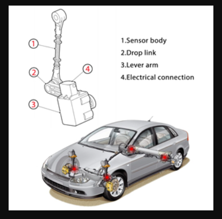
The height sensor itself is usually a potentiometer, essentially a variable resistor. As the suspension moves, a lever arm connected to the sensor rotates, changing the resistance value. This resistance is converted into a voltage signal that's sent to the control module (typically the Body Control Module or BCM for headlights, or a dedicated suspension control module). The module interprets this voltage as a specific height.
The "Right Rear Height Sensor Circuit Out of Range" code means the voltage signal being sent by the right rear sensor is either significantly higher or lower than expected, or completely missing. This can trigger warning lights on the dashboard and, in the case of auto-leveling headlights, cause the headlights to point too high or too low.
Decoding the "Out of Range" Code
When you see "Out of Range," it broadly translates to one of two possibilities:
- Circuit High: The voltage reading is higher than the expected maximum value. This usually indicates a short to voltage somewhere in the sensor circuit.
- Circuit Low: The voltage reading is lower than the expected minimum value. This often means a short to ground, an open circuit (broken wire), or a faulty sensor.
It's essential to know that simply replacing the sensor without diagnosing the root cause rarely fixes the problem permanently. You're more likely to be addressing a symptom rather than the underlying issue.
Troubleshooting Steps: A Systematic Approach
Here's a step-by-step guide to diagnosing the "Right Rear Height Sensor Circuit Out of Range" code. Always disconnect the negative battery terminal before working on electrical components. Safety first!
1. Visual Inspection
This is the easiest and often most revealing step. Carefully inspect the following:
- The Sensor Itself: Look for physical damage to the sensor body, the lever arm, or its mounting bracket. Is the arm bent, broken, or detached? Is the sensor dangling or loosely mounted?
- Wiring and Connectors: Trace the wiring harness from the sensor up to the nearest connector. Look for any signs of damage, such as cuts, abrasions, melted insulation, or corrosion. Pay close attention to areas where the wiring harness might rub against the chassis or suspension components. Check the connector itself for bent or corroded pins. Make sure the connector is securely fastened to the sensor.
- The Linkage: Examine the linkage between the suspension and the sensor arm. Make sure it's not binding, damaged, or disconnected. Sometimes debris can get lodged in the linkage, preventing it from moving freely.
Pro Tip: A bright flashlight and a small inspection mirror can be invaluable for reaching and inspecting hard-to-see areas.
2. Connector Inspection and Cleaning
Disconnect the connector at the height sensor. Use a multimeter set to measure resistance (Ohms) to check the terminals in the connector for corrosion. If you find any, clean the terminals with electrical contact cleaner. You can also use a small wire brush or terminal cleaning tool to remove stubborn corrosion. Apply dielectric grease to the connector terminals before reconnecting to prevent future corrosion.
3. Voltage and Ground Checks
This step requires a multimeter and the wiring diagram for your specific Altima model. You can usually find these diagrams online or in a repair manual (Haynes or Chilton are good resources). Identify the following wires at the height sensor connector:
- Power Wire: This should typically be a 5V reference voltage supplied by the control module. With the ignition on (but engine off), use your multimeter to measure the voltage between this wire and ground. You should see approximately 5V. If you don't, the problem lies further upstream, possibly in the wiring harness or the control module itself.
- Ground Wire: Use your multimeter set to measure resistance (Ohms). Connect one lead to the ground wire and the other to a known good ground point on the chassis. The resistance should be very close to zero (less than 1 Ohm). If the resistance is high, there's a grounding issue. Trace the ground wire back to its grounding point and clean the connection.
- Signal Wire: This wire carries the voltage signal from the sensor back to the control module. We'll check this in the next step.
4. Signal Wire Continuity and Short Checks
This step checks the integrity of the signal wire. Disconnect the connector at both the height sensor and the control module. This is crucial to prevent damage to the control module. Now, use your multimeter set to measure resistance (Ohms) to perform the following checks:
- Continuity Test: Connect one lead of your multimeter to the signal wire at the height sensor connector and the other lead to the corresponding pin at the control module connector. You should see low resistance (close to zero Ohms), indicating a continuous wire. If you see high resistance or an open circuit, the wire is broken or damaged somewhere along its length.
- Short to Ground Test: Connect one lead of your multimeter to the signal wire at the height sensor connector and the other lead to a known good ground point on the chassis. You should see infinite resistance (OL or a very high value), indicating that the signal wire is not shorted to ground. If you see low resistance, the signal wire is shorted to ground.
- Short to Voltage Test: This is a bit trickier and requires carefully checking the wiring diagram to identify any nearby voltage-carrying wires. Connect one lead of your multimeter to the signal wire at the height sensor connector and the other lead to any nearby voltage-carrying wire (with the ignition off). You should see infinite resistance. If you see low resistance, the signal wire is shorted to a voltage source.
If you find a broken or shorted wire, you'll need to repair or replace that section of the wiring harness.
5. Sensor Output Test
Reconnect the height sensor connector. With the ignition on (but engine off), use your multimeter to measure the voltage on the signal wire while manually moving the sensor arm up and down. The voltage reading should change smoothly and linearly as you move the arm. If the voltage remains constant or jumps erratically, the sensor itself is likely faulty.
6. Control Module
If you've performed all the above tests and the wiring and sensor seem to be functioning correctly, the problem *might* be with the control module itself. However, this is the least likely scenario. Control modules are relatively robust, and it's far more common for the issue to be a faulty sensor or damaged wiring. Before condemning the control module, double-check all your previous tests. If you're still convinced the module is the culprit, consult a qualified technician or consider replacing it with a known good unit.
Clearing the Code and Testing
After you've made any repairs, clear the diagnostic trouble code (DTC) using an OBD-II scanner. Then, test the system to ensure that the code doesn't return. For auto-leveling headlights, this might involve loading the rear of the vehicle to simulate a heavy load and observing whether the headlights adjust properly. For vehicles with electronically controlled suspension, monitor the ride quality to see if it has improved.
Final Thoughts
Troubleshooting electrical issues can be challenging, but by following a systematic approach and taking your time, you can often diagnose and repair the problem yourself. Remember to always prioritize safety, use the correct tools, and consult the wiring diagram for your specific vehicle. Good luck, and happy wrenching!