Transmission Sensor Diagnostics And Replacement Guide
The modern automatic transmission is a marvel of engineering, a complex dance of hydraulics, electronics, and precise mechanical components all working in concert to deliver smooth and efficient power transfer. At the heart of this intricate system are a multitude of sensors, constantly monitoring various parameters and feeding data to the transmission control module (TCM). When these sensors fail, the consequences can range from minor inconveniences to complete transmission failure. This guide will provide an in-depth look at diagnosing and replacing common transmission sensors, equipping you with the knowledge to troubleshoot issues and potentially save on costly repair bills.
Understanding the Role of Transmission Sensors
Transmission sensors are essentially the eyes and ears of the TCM. They provide critical data that allows the TCM to make informed decisions about shift timing, torque converter lockup, and overall transmission operation. Without accurate sensor readings, the TCM resorts to default strategies, often resulting in harsh shifting, reduced fuel economy, and potential damage to internal components. Let's explore some of the most common types of transmission sensors:
Speed Sensors (Input and Output)
These sensors, often inductive or Hall-effect sensors, measure the rotational speed of various shafts within the transmission. The input speed sensor (ISS) monitors the speed of the turbine shaft coming from the torque converter, while the output speed sensor (OSS) monitors the speed of the output shaft going to the differential. By comparing these speeds, the TCM can determine the transmission's gear ratio and detect slippage. A faulty speed sensor can trigger diagnostic trouble codes (DTCs) such as P0720 (Output Speed Sensor Circuit Malfunction) or P0715 (Input/Turbine Speed Sensor Circuit Malfunction). Symptoms can include erratic shifting, failure to shift, or the transmission entering limp mode.
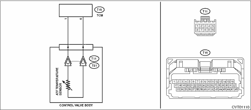
Temperature Sensor (Transmission Fluid Temperature - TFT)
The TFT sensor monitors the temperature of the transmission fluid. This is crucial because fluid viscosity changes significantly with temperature. The TCM uses this data to adjust shift points and torque converter clutch engagement. Overheating can severely damage a transmission, and the TCM will often take preventative measures, such as delaying shifts or locking the torque converter, if the TFT sensor reports excessively high temperatures. Common DTCs related to the TFT sensor include P0711 (Transmission Fluid Temperature Sensor Range/Performance) and P0712 (Transmission Fluid Temperature Sensor Low Input). A faulty TFT sensor can lead to harsh shifting, delayed shifts, and potentially overheating of the transmission.
Pressure Sensors (Transmission Fluid Pressure - TFPS)
Some advanced transmissions utilize pressure sensors to monitor the hydraulic pressure within the various circuits of the valve body. These sensors provide valuable feedback on the performance of the hydraulic system, allowing the TCM to diagnose issues such as valve body malfunctions or worn solenoids. DTCs related to TFPS can be more complex to diagnose, but often involve codes indicating incorrect pressure readings or solenoid performance issues. These problems manifest as erratic shifting, slipping, or complete failure to shift.
Shift Solenoids (Valve Body)
Although not technically sensors, shift solenoids are often considered part of the overall transmission sensor system because they are electronically controlled actuators that rely on feedback from other sensors. These solenoids control the flow of hydraulic fluid to various clutches and bands, enabling the transmission to shift gears. A malfunctioning solenoid can prevent the transmission from shifting into a particular gear or cause harsh shifts. DTCs such as P0750 (Shift Solenoid A Malfunction) or P0755 (Shift Solenoid B Malfunction) indicate problems with specific solenoids. Replacing shift solenoids often requires removing the transmission pan and accessing the valve body.
Diagnosing Transmission Sensor Problems
Before replacing any sensor, it's crucial to properly diagnose the problem. Here's a step-by-step approach:
- Scan for Diagnostic Trouble Codes (DTCs): Use an OBD-II scanner to retrieve any stored DTCs. This is the first and most important step. Write down all codes, as they provide valuable clues about the source of the problem.
- Research the DTCs: Consult a reliable repair manual or online database to understand the meaning of each DTC and potential causes. Be aware that a single symptom can sometimes trigger multiple codes.
- Inspect Wiring and Connectors: Carefully inspect the wiring and connectors associated with the suspected sensor. Look for signs of damage, corrosion, or loose connections. Use a multimeter to check for continuity and voltage at the sensor connector. Often, a simple wiring issue can mimic a faulty sensor.
- Check Sensor Resistance: Most transmission sensors have a specific resistance range. Use a multimeter to measure the sensor's resistance and compare it to the manufacturer's specifications. An out-of-range reading suggests a faulty sensor. Consult the vehicle's service manual for the correct resistance values and testing procedure.
- Live Data Analysis: Using a scan tool capable of displaying live data, monitor the sensor's output while the vehicle is running. Look for erratic readings, dropouts, or values that don't correspond to the expected behavior. For example, monitor the TFT sensor reading as the engine warms up to see if it's increasing gradually and smoothly.
- Component Testing: Some sensors, such as speed sensors, can be tested by manually rotating the shaft they're monitoring and observing the corresponding signal on a scan tool or oscilloscope. This can help determine if the sensor is generating a signal and if the signal is consistent.
- Consider Fluid Condition: While not directly related to sensor diagnosis, the condition of the transmission fluid can significantly impact transmission performance. Check the fluid level and condition. Dark, burnt, or contaminated fluid can contribute to shifting problems and may indicate underlying issues that need to be addressed.
Important Note: Always refer to the vehicle's specific service manual for detailed diagnostic procedures and specifications. Generic information may not be accurate for all makes and models.
Replacing a Transmission Sensor
Once you've confirmed that a sensor is faulty, replacing it is usually a straightforward process. However, it's important to follow these steps carefully:
- Gather Necessary Tools and Parts: Obtain the correct replacement sensor, as well as any necessary tools, such as sockets, wrenches, screwdrivers, and a torque wrench. Also, have a drain pan ready if you need to drain any transmission fluid.
- Disconnect the Battery: This is a crucial safety precaution to prevent electrical shocks and accidental activation of the transmission.
- Locate the Sensor: Refer to the service manual to locate the faulty sensor. They are often located externally on the transmission case, but some may be inside the transmission pan.
- Disconnect the Electrical Connector: Carefully disconnect the electrical connector from the sensor. Be gentle to avoid damaging the connector or wiring.
- Remove the Old Sensor: Use the appropriate wrench or socket to remove the old sensor. Some sensors may be secured with a bolt or screw.
- Install the New Sensor: Install the new sensor, making sure it's properly seated and tightened to the manufacturer's specified torque. Overtightening can damage the sensor or the transmission case.
- Reconnect the Electrical Connector: Reconnect the electrical connector to the new sensor, ensuring it's securely latched.
- Check Transmission Fluid Level (If Necessary): If you had to drain any transmission fluid, refill it to the correct level according to the vehicle's service manual.
- Reconnect the Battery: Reconnect the battery.
- Clear DTCs: Use an OBD-II scanner to clear any DTCs that were stored in the TCM.
- Test Drive: Perform a test drive to verify that the transmission is shifting smoothly and that the problem has been resolved. Monitor the sensor data with a scan tool to confirm that the new sensor is functioning correctly.
Caution: When working on the transmission, be extremely careful to avoid contaminating the internal components with dirt or debris. Cleanliness is essential for proper transmission operation.
Preventative Maintenance
While sensors can fail unexpectedly, proper maintenance can help extend their lifespan and prevent premature failure. Regularly changing the transmission fluid according to the manufacturer's recommendations is crucial. Clean fluid helps to keep the sensors clean and operating efficiently. Also, avoid harsh driving habits, such as frequent hard acceleration and deceleration, as this can put unnecessary stress on the transmission and its components.
Conclusion
Diagnosing and replacing transmission sensors can seem daunting, but with a systematic approach and a basic understanding of how these sensors function, it's a task that many DIYers can tackle. Remember to always prioritize safety, consult the vehicle's service manual, and take your time. By following the steps outlined in this guide, you can potentially save money and gain a deeper appreciation for the intricate workings of the modern automatic transmission. Understanding how your vehicle works empowers you to make informed decisions about its care and maintenance.