Turn Signal Wiring Schematics And Circuit Protection
Alright folks, let's talk turn signals. It's one of those things you don't really think about until they stop working, and then suddenly you realize how much you rely on them – and how dangerous it is without them! Whether you're dealing with a single bulb that refuses to blink, or a complete system failure, understanding the basics of turn signal wiring and circuit protection is key to getting back on the road safely. This guide will walk you through troubleshooting common issues, interpreting wiring schematics, and ensuring your turn signal circuits are properly protected.
Understanding the Basics: How Turn Signals Work
At its core, a turn signal system is fairly simple. It involves a power source (your car's battery), a switch (the turn signal stalk on your steering column), a flasher relay (which makes the lights blink), the lights themselves (front and rear), and the wiring that connects everything together. Here's a breakdown of each component:
- Battery: Provides the electrical power for the entire system.
- Turn Signal Switch: Allows you to select left or right turn signals, activating the corresponding circuits.
- Flasher Relay (or Flasher Module): This is the heart of the blinking action. It's an electrical device that interrupts the current flow to the lights, causing them to flash on and off. Older cars often use thermal flasher relays, while newer cars may use electronic flasher modules controlled by the vehicle's computer.
- Turn Signal Bulbs: The light source that indicates your intention to turn.
- Wiring: The network of wires that connects all the components, allowing electricity to flow.
- Fuses: A critical safety component that protects the circuit from overload. We'll delve deeper into this later.
Common Turn Signal Problems and Troubleshooting
Here are some common issues you might encounter with your turn signals, and how to diagnose them:
Problem: No Turn Signals at All
If none of your turn signals are working (front, rear, left, or right), the first place to check is the fuse. Consult your owner's manual to locate the fuse specifically for the turn signals. A blown fuse is often the culprit. If the fuse is blown, replace it with a new fuse of the same amperage. If the new fuse blows immediately, you have a short circuit somewhere in the system, and you'll need to investigate further.
If the fuse is good, the next suspect is the flasher relay. You can often locate the flasher relay by listening for a clicking sound when you activate the turn signals. If you don't hear a click, the relay might be faulty. You can try replacing the flasher relay to see if that resolves the issue. Consult your owner's manual for the flasher relay's location.
Problem: One Turn Signal Not Working (Front or Rear)
If only one turn signal is out (for example, the front left or the rear right), the most likely cause is a burned-out bulb. Replace the bulb with the correct type and see if that fixes the problem. Make sure to check the bulb socket for corrosion, which can prevent good contact. Clean the socket with a wire brush or electrical contact cleaner.
If the bulb is good and the socket is clean, the problem might be in the wiring. Check the wiring harness and connectors near the affected light for any signs of damage, corrosion, or loose connections. Use a multimeter to check for voltage at the bulb socket when the turn signal is activated.
Problem: Turn Signals Blink Too Fast (Hyperflashing)
Hyperflashing (when the turn signals blink much faster than normal) usually indicates that one of the turn signal bulbs is burned out. The increased flash rate is a built-in warning system. Replace the burned-out bulb and the hyperflashing should stop. However, sometimes it can indicate a low resistance bulb being used or that there is a bad ground on one of the turn signal circuits.
If all the bulbs are working, the hyperflashing could be caused by an incorrect flasher relay. Some cars require a specific type of flasher relay, especially if you've switched to LED bulbs. LED bulbs draw less current than traditional incandescent bulbs, which can confuse the flasher relay and cause hyperflashing. In this case, you may need to install a flasher relay designed for LED bulbs, or add resistors to the circuit to simulate the load of incandescent bulbs.
Problem: Turn Signals Work Intermittently
Intermittent turn signal problems are often caused by loose connections, corrosion, or damaged wiring. Carefully inspect all the wiring and connectors in the turn signal circuit, paying close attention to areas that are exposed to the elements or subject to vibration. Clean any corroded connections with a wire brush and electrical contact cleaner. You might consider applying some dielectric grease to the connections to help prevent future corrosion.
Decoding Turn Signal Wiring Schematics
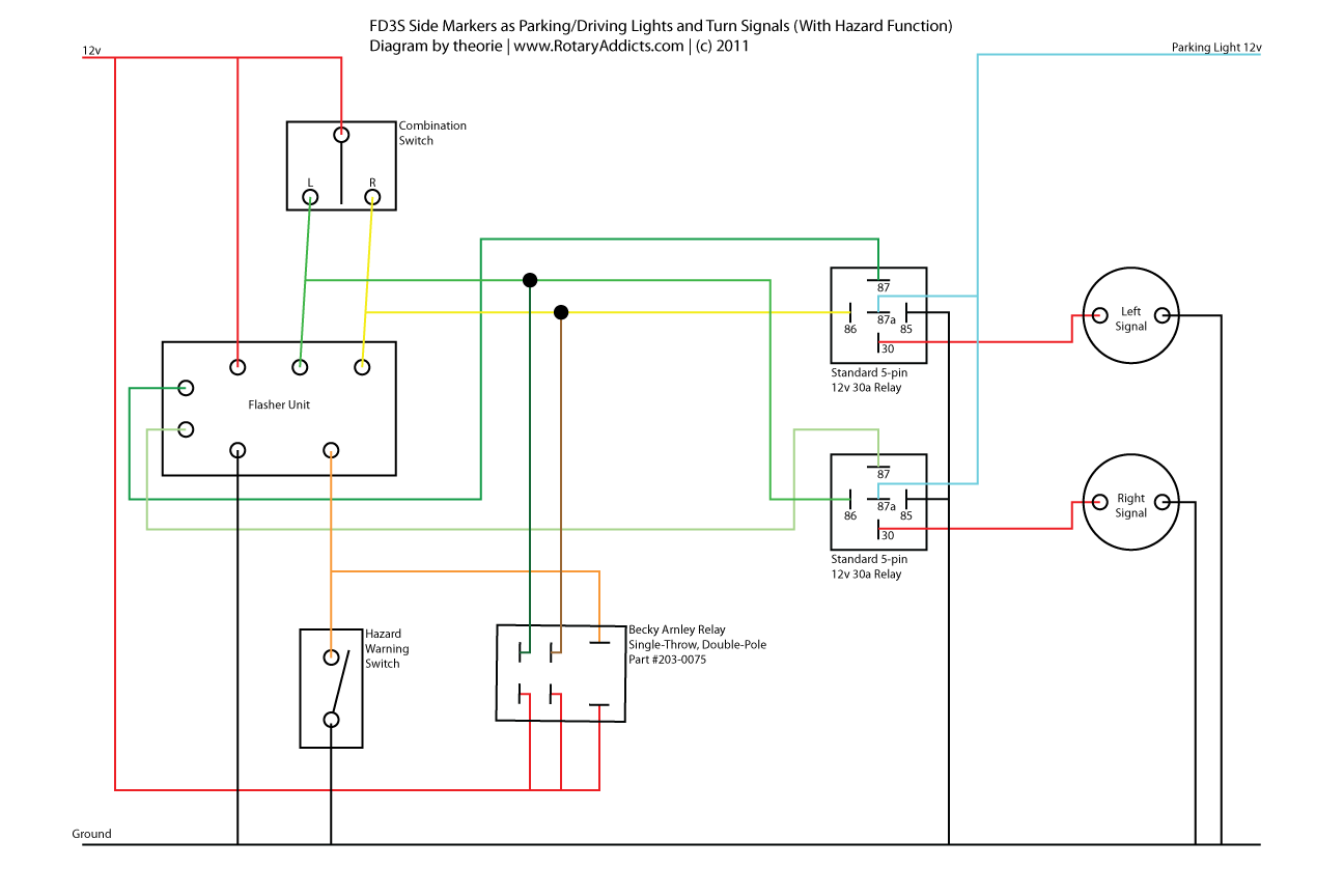
When troubleshooting electrical problems, a wiring schematic is your best friend. A wiring schematic is a diagram that shows the electrical circuits in your car. It uses symbols to represent different components and lines to represent the wires that connect them. Understanding how to read a wiring schematic can save you a lot of time and frustration.
Here are some key things to look for in a turn signal wiring schematic:
- Power Source: Usually labeled as "Battery" or "B+"
- Ground: Indicated by a ground symbol (usually a series of horizontal lines).
- Turn Signal Switch: Shows how the switch directs power to the left or right turn signal circuits.
- Flasher Relay: Often labeled as "Flasher" or "Turn Signal Relay."
- Turn Signal Lights: Shows the front and rear turn signal lights for both the left and right sides.
- Wire Colors: Wiring schematics often use different colors to identify different wires. A color code chart will be included in the schematic.
- Fuse: Usually labeled as "Fuse" and shows the amperage rating of the fuse.
When tracing a circuit on a wiring schematic, start at the power source and follow the path of the current through the various components until it reaches the ground. This will help you understand how the circuit works and identify potential points of failure.
Pro Tip: You can usually find wiring schematics for your specific car model in a repair manual (like Haynes or Chilton) or online through subscription-based automotive repair databases.
Circuit Protection: Fuses and More
Circuit protection is crucial for preventing damage to your electrical system and reducing the risk of fire. The primary form of circuit protection in a turn signal system is the fuse. A fuse is a small, inexpensive device that contains a thin wire designed to melt and break the circuit if the current exceeds a certain level. This protects the other components in the circuit from overheating and potentially causing damage or a fire.
It's important to use the correct amperage fuse for your turn signal circuit. Using a fuse with a higher amperage rating than specified can allow too much current to flow through the circuit, which could damage the wiring or other components. Using a fuse with a lower amperage rating than specified will cause the fuse to blow prematurely.
In addition to fuses, some cars also use circuit breakers to protect the turn signal circuits. A circuit breaker is similar to a fuse, but it can be reset after it trips. Circuit breakers are often used in circuits that are subject to intermittent overloads.
Here are some tips for working with fuses:
- Always disconnect the battery before working on any electrical circuits.
- Use a fuse puller to remove fuses. This will prevent you from accidentally damaging the fuse box or other components.
- Inspect the fuse carefully before replacing it. Look for signs of damage, such as a broken wire or a burned spot.
- If a fuse blows repeatedly, there is a problem in the circuit that needs to be addressed. Don't just keep replacing the fuse.
Tools and Approximate Repair Costs
Here's a list of tools you might need for troubleshooting and repairing turn signal problems:
- Multimeter
- Fuse puller
- Wire stripper/crimper
- Electrical tape
- Wire brush
- Electrical contact cleaner
- Screwdrivers (various sizes)
- Pliers
- Wiring schematic for your vehicle
Approximate repair costs can vary depending on the nature of the problem and whether you do the work yourself or take it to a mechanic. Here's a rough estimate:
- Replacing a bulb: $5 - $15 (DIY)
- Replacing a fuse: $2 - $5 (DIY)
- Replacing a flasher relay: $10 - $30 (DIY)
- Repairing a damaged wire: $10 - $50 (DIY, depending on complexity)
- Professional diagnosis and repair at a mechanic: $80 - $200+ (depending on the problem and labor rates)
Conclusion
Troubleshooting turn signal problems can seem daunting, but with a basic understanding of the system and the right tools, you can often diagnose and repair the issue yourself. Remember to prioritize safety when working with electrical systems, and don't hesitate to consult a qualified mechanic if you're unsure about anything. Safe driving starts with working turn signals!
Important Safety Note: Always disconnect the negative terminal of your car battery before working on any electrical components to avoid accidental shocks or damage to the vehicle's electrical system.