Wiring Harness Pinout Documentation And Circuit Protection Analysis
The unsung hero of any complex electromechanical system, be it a car, a plane, or an industrial robot, is the wiring harness. These intricate bundles of wires are the circulatory system of electricity, carrying power and data throughout the machine. Understanding wiring harness pinout documentation and analyzing circuit protection measures is crucial for anyone delving into electrical troubleshooting, modification, or even basic repair. This article will guide you through the intricacies of these topics, equipping you with the knowledge to dissect and understand these essential components.
Understanding Wiring Harness Pinout Documentation
Think of a wiring harness as a highly organized and carefully documented extension cord, albeit one with dozens or even hundreds of individual conductors. The pinout documentation is the roadmap that guides you through this electrical maze. It details exactly which wire connects to which terminal within each connector of the harness. Without it, you're essentially flying blind.
Decoding the Schematics
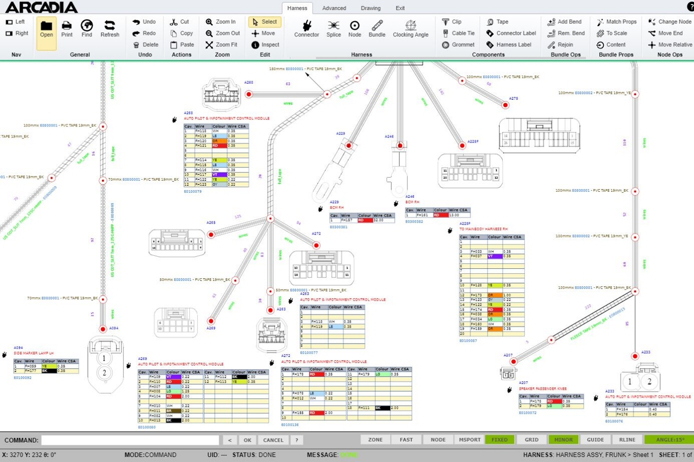
Pinout documentation typically comes in the form of schematics, diagrams, or tables. These documents provide a standardized way to represent the wiring configuration. Let's break down the key elements:
- Connector Identification: Each connector is assigned a unique identifier, often a combination of letters and numbers (e.g., X102, CN5). This allows you to quickly locate the physical connector on the harness. Pay close attention to the connector type, whether it's a standard automotive connector (like a Molex MX150) or a more specialized industrial variant.
- Pin Numbers: Each terminal within the connector is also numbered. These numbers are usually printed directly on the connector housing, but sometimes you'll need a magnifying glass to see them! The pinout documentation precisely correlates each pin number with its corresponding wire.
- Wire Colors: Wire colors are standardized across many industries, but variations can exist between manufacturers. The pinout document will specify the color of each wire connected to each pin. Often, a primary color is combined with a tracer color (e.g., Blue/White, Green/Black).
- Wire Gauge: The wire gauge, measured in American Wire Gauge (AWG), indicates the wire's current-carrying capacity. A lower AWG number corresponds to a thicker wire and higher current capacity. This is critical for ensuring that each wire can handle the load of the circuit it serves.
- Circuit Designation: This describes the function of the circuit connected to that particular pin. For example, "Headlight High Beam," "Fuel Pump Relay Control," or "Sensor Ground." Understanding the circuit designation is paramount for troubleshooting issues.
- Grounding Points: Grounding is crucial for electrical safety and proper circuit operation. The pinout documentation will clearly indicate which pins are connected to ground, and often specify the exact grounding point on the chassis or engine block.
Example: Imagine a connector labeled "X205" with 10 pins. The pinout documentation might state that Pin 1 (Red wire, 18 AWG) is connected to "Ignition Switch Power," Pin 2 (Black wire, 18 AWG) is connected to "Chassis Ground," Pin 5 (Yellow/Black wire, 20 AWG) is connected to "Fuel Injector 1 Control," and so on.
Reading Complex Schematics
For complex wiring harnesses, the pinout documentation may be presented as a large schematic diagram. These diagrams can appear daunting at first, but they follow a logical structure. The diagram typically shows the various connectors, wires, and components interconnected. Tracing a circuit involves following the lines representing wires from one component to another, paying attention to connector pin numbers and wire colors along the way. Software tools can often aid in navigating these schematics, allowing you to zoom in on specific sections and search for components or circuits.
Pro Tip: Always cross-reference the pinout documentation with the actual wiring harness. Visual inspection is crucial to verify that the wire colors and pin connections match the documentation. Manufacturing errors or previous repairs can sometimes lead to discrepancies.
Circuit Protection Analysis
Circuit protection is the critical safety net that prevents electrical damage and potential fires. Understanding the different types of circuit protection and how they function is essential for maintaining the integrity of the electrical system.
Fuses: The Sacrificial Lambs
Fuses are perhaps the most common type of circuit protection. They are designed to sacrifice themselves by melting and breaking the circuit when the current exceeds a predetermined threshold. This prevents excessive current from flowing through the wires and components, which could lead to overheating and damage.
- Fuse Types: Fuses come in various shapes and sizes, including blade fuses (ATO, Mini, Maxi), glass tube fuses, and cartridge fuses. Each type has a specific current rating (measured in Amperes) that indicates the maximum current it can handle before blowing.
- Fuse Placement: Fuses are typically located in fuse boxes strategically positioned throughout the vehicle or machine. The fuse box layout is usually documented in the owner's manual or a separate fuse box diagram.
- Fuse Selection: Choosing the correct fuse rating is crucial. Using a fuse with a rating that is too low will cause it to blow frequently under normal operating conditions. Using a fuse with a rating that is too high defeats the purpose of circuit protection and can lead to serious damage. The pinout documentation or a separate circuit diagram will specify the correct fuse rating for each circuit.
Circuit Breakers: The Reset Button
Circuit breakers are similar to fuses in that they interrupt the circuit when the current exceeds a threshold. However, unlike fuses, circuit breakers can be reset after they trip, allowing the circuit to be restored without replacing a component. They typically use a bimetallic strip or an electromagnet to detect overcurrent conditions.
- Types of Circuit Breakers: Common types include thermal circuit breakers, magnetic circuit breakers, and electronic circuit breakers.
- Reset Mechanisms: Circuit breakers can be reset manually (by pressing a button or flipping a switch) or automatically (after a certain cooling-off period).
- Applications: Circuit breakers are often used in circuits that are likely to experience temporary overloads, such as motor circuits or lighting circuits.
Overload Relays: Protecting Motors and Equipment
Overload relays are specialized protection devices used primarily to protect electric motors from overheating due to overloads. They monitor the motor current and trip when the current exceeds the motor's rated current for a prolonged period.
- Thermal Overload Relays: These relays use a bimetallic strip that heats up due to the motor current. When the strip reaches a certain temperature, it trips the relay, disconnecting power to the motor.
- Electronic Overload Relays: These relays use electronic sensors to monitor the motor current and provide more accurate and reliable overload protection. They often offer advanced features such as adjustable trip settings and fault diagnostics.
Other Protection Mechanisms
Besides fuses, circuit breakers, and overload relays, other circuit protection mechanisms include:
- Transient Voltage Suppressors (TVS Diodes): These devices protect sensitive electronic components from voltage spikes caused by lightning strikes, inductive switching, or electrostatic discharge.
- Surge Protectors: Similar to TVS diodes, surge protectors provide protection against larger voltage surges.
- Ground Fault Circuit Interrupters (GFCIs): GFCIs are designed to detect ground faults, which occur when current flows through an unintended path to ground. They are commonly used in wet locations, such as bathrooms and kitchens, to prevent electric shock.
Analyzing Circuit Protection Schemes
Analyzing circuit protection involves understanding the types of protection devices used, their current ratings, and their placement within the circuit. This analysis is crucial for identifying potential weaknesses in the protection scheme and ensuring that the system is adequately protected against overcurrents, voltage surges, and ground faults.
Safety First: Always disconnect the power source before working on any electrical system. Use insulated tools and follow proper safety procedures to avoid electric shock. If you are not comfortable working with electricity, consult a qualified electrician.
By understanding wiring harness pinout documentation and analyzing circuit protection measures, you gain invaluable insights into the inner workings of complex electromechanical systems. This knowledge empowers you to troubleshoot electrical problems effectively, make informed modifications, and ensure the long-term reliability of the equipment you are working with.