Abs Light What Does It Mean
Alright, let's talk about that dreaded ABS light on your dashboard. Seeing that illuminated icon can be unsettling, but understanding the Anti-lock Braking System (ABS) and how it functions is the first step towards diagnosing and potentially resolving the issue. This article will provide a detailed look into the ABS system, its components, operation, troubleshooting, and safety precautions. Think of this as your guide to decoding that ABS warning light. With this information, you'll be better equipped to tackle repairs, further your automotive knowledge, and make informed decisions about your vehicle's safety.
Purpose of Understanding the ABS
Why bother diving deep into the intricacies of ABS? Well, several reasons. First and foremost, it’s about safety. Your ABS is a critical safety system designed to prevent wheel lockup during hard braking, allowing you to maintain steering control. Understanding the system enables you to better diagnose issues and ensure it's functioning correctly. Secondly, for the DIY mechanic, understanding the ABS can save you money. Instead of immediately taking your car to a shop, you can perform preliminary checks and potentially identify the problem yourself, leading to a more informed interaction with a mechanic or even a DIY repair. Lastly, for the experienced car owner or modder, knowledge is power. Understanding the ABS allows you to appreciate its capabilities and limitations, especially when considering performance modifications that might affect braking performance.
Key Specifications and Main Parts of the ABS
The specific components and specifications of an ABS system will vary slightly depending on the vehicle make, model, and year. However, the core elements remain consistent. Here’s a breakdown:
- Wheel Speed Sensors (WSS): Located at each wheel, these sensors monitor the rotational speed of the wheel. They typically use a toothed tone ring and a magnetic sensor to generate an electrical signal proportional to wheel speed. WSS readings are critical for ABS operation.
- ABS Control Module (ECU/Module): The brain of the system, the ABS control module receives signals from the wheel speed sensors and other inputs (like the brake pedal position sensor). It analyzes this data to determine if a wheel is locking up during braking. The module uses a Proportional-Integral-Derivative (PID) control loop to determine how much pressure to apply to each brake caliper.
- Hydraulic Control Unit (HCU): This unit contains valves and a pump that regulate brake pressure to each wheel based on the commands from the ABS control module. It allows for individual wheel braking force modulation. The HCU includes:
- Solenoid Valves: These valves open and close to either increase, decrease, or maintain brake pressure at each wheel.
- Pump and Motor: Provides the necessary hydraulic pressure to reduce brake pressure when a wheel is about to lock up.
- Accumulator: Stores hydraulic pressure for rapid brake pressure adjustments.
- Brake Pedal Position Sensor: This sensor indicates the driver's intention to brake and the force applied. It is an input to the ABS ECU that helps predict braking scenarios.
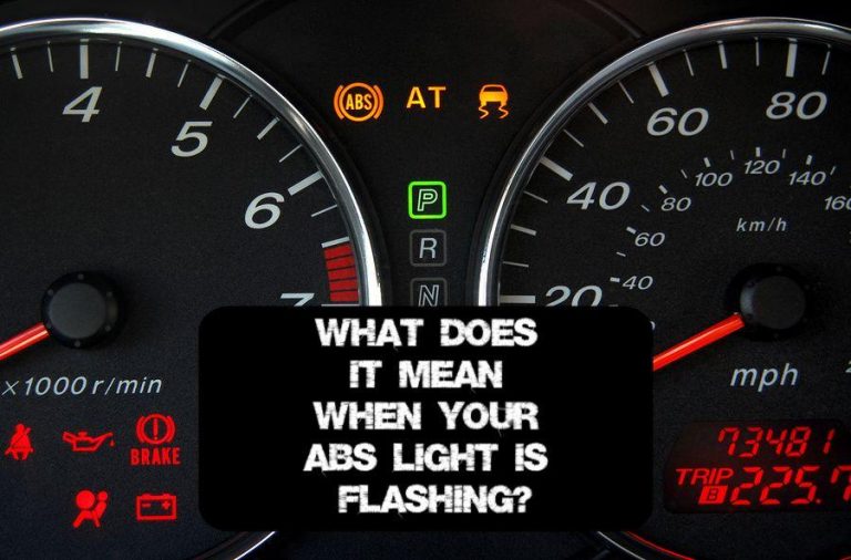
- ABS Warning Light: Located on the instrument panel, this light illuminates when the ABS system detects a fault.
Symbols, Lines, and Colors in ABS Diagrams
Understanding ABS diagrams involves interpreting the symbols and conventions used to represent different components and connections. A typical ABS schematic will use standardized electrical symbols for sensors, valves, and electronic components. Lines represent wiring and hydraulic lines. Here’s a general guide:
- Solid Lines: Typically represent electrical wiring. Heavier lines may indicate power or ground circuits.
- Dashed Lines: Often represent communication buses, like the CAN (Controller Area Network) bus, which allows the ABS control module to communicate with other vehicle systems.
- Different Colors: Wiring diagrams often use color-coded wires to help identify specific circuits. For example, a red wire might represent a power supply, while a black wire might represent ground.
- Component Symbols: Look for standard symbols for resistors, capacitors, transistors, diodes, and integrated circuits. Wheel speed sensors are often represented by a circle with a toothed wheel inside.
- Hydraulic Lines: Often depicted as thicker lines than electrical wires, and may be color-coded to indicate pressure levels (e.g., red for high pressure, blue for low pressure).
How ABS Works
The fundamental principle behind ABS is preventing wheel lockup during braking. When a wheel locks up, it loses traction, making steering impossible. ABS prevents this by modulating the brake pressure applied to each wheel. Here’s a step-by-step explanation:
- Normal Braking: During normal braking, the ABS system monitors the wheel speed sensors. If all wheels are rotating at roughly the same speed and decelerating at a similar rate, the ABS system remains inactive.
- Impending Lockup: If one or more wheels begin to decelerate rapidly, indicating an impending lockup, the ABS control module detects this.
- Pressure Modulation: The ABS control module signals the hydraulic control unit (HCU) to reduce brake pressure to the affected wheel(s). This is achieved by opening and closing solenoid valves within the HCU.
- Pressure Increase/Hold: The HCU cycles between reducing, holding, and increasing brake pressure to the wheel(s) rapidly. This allows the wheel(s) to regain traction without fully locking up.
- Repetition: This process repeats several times per second, allowing the driver to maintain steering control while braking hard. You will typically feel a pulsating sensation in the brake pedal as the ABS system engages.
In essence, the ABS system mimics what an experienced driver would do when encountering a skid – rapidly pumping the brakes to prevent lockup. However, the ABS system does it much faster and more precisely than any human could.
Real-World Use: Basic Troubleshooting Tips
When the ABS light illuminates, it indicates that the ABS system has detected a fault. Here are some basic troubleshooting steps you can take:
- Visual Inspection: Check the wheel speed sensor wiring and connectors at each wheel for damage or corrosion. Look for obvious signs of physical damage to the sensors themselves.
- Scan for Codes: Use an OBD-II scanner to retrieve the Diagnostic Trouble Codes (DTCs) stored in the ABS control module. These codes provide valuable clues about the nature of the fault. Common codes relate to wheel speed sensor issues, hydraulic control unit problems, or control module failures.
- Wheel Speed Sensor Testing: Using a multimeter, you can test the resistance of the wheel speed sensors. Consult your vehicle's service manual for the correct resistance values. You can also use a scope to view the WSS output signal to see if it has any breaks in the sine wave.
- Hydraulic Control Unit Check: Listen for the ABS pump motor activating when the system performs a self-test (usually when the ignition is turned on). If you don't hear the pump, it could indicate a problem with the motor or the HCU itself.
- Check Brake Fluid Level: Low brake fluid can sometimes trigger the ABS light. Ensure the brake fluid reservoir is filled to the appropriate level.
- Clear Codes and Retest: After addressing any identified issues, clear the DTCs and retest the system. If the ABS light remains off, the problem is likely resolved.
Safety Precautions
Working on the ABS system involves handling potentially hazardous components. Exercise extreme caution and follow these safety guidelines:
- Disconnect the Battery: Before working on any electrical components, disconnect the negative battery terminal to prevent electrical shock or damage to the system.
- Handle Hydraulic Fluid Carefully: Brake fluid is corrosive and can damage painted surfaces. Wear gloves and eye protection when handling brake fluid. Clean up any spills immediately.
- Be Aware of High-Pressure Components: The hydraulic control unit contains high-pressure brake fluid. Do not attempt to disassemble the HCU without proper training and equipment. Incorrect disassembly can result in serious injury.
- Proper Bleeding Procedures: After working on the hydraulic system, it's crucial to bleed the brakes properly to remove air from the lines. Follow the manufacturer's recommended bleeding procedure. Special scan tools are often required to activate the ABS pump during the bleeding process.
- Consult a Professional: If you're not comfortable working on the ABS system, or if you encounter complex issues that you can't diagnose, seek assistance from a qualified mechanic.
Working with the ABS system requires caution and precision. While this guide provides a good starting point, remember to consult your vehicle's specific repair manual for detailed instructions and specifications. Always prioritize safety and seek professional assistance when needed.
We have a detailed ABS system diagram file available for download. This diagram includes specific component locations, wiring schematics, and hydraulic layouts. This resource will be invaluable for further understanding and troubleshooting your vehicle's ABS system.