At What Speed Does Airbags Deploy
Understanding the deployment speed of airbags is crucial for anyone involved in vehicle repairs, modifications, or even just understanding the safety systems of their car. This knowledge isn't just academic; it directly impacts how you approach diagnosing issues, working around the system safely, and appreciating the physics involved in occupant protection. This article will delve into the specifics of airbag deployment speed, the underlying technology, and practical considerations for DIY enthusiasts and mechanics alike.
Airbag Deployment Speed: The Critical Numbers
The speed at which an airbag deploys is not a fixed value. It's a carefully engineered range designed to offer optimal protection in various collision scenarios. Generally, driver-side airbags deploy at speeds between 100 and 220 mph (160 to 350 km/h), while passenger-side airbags can deploy at higher speeds, sometimes exceeding 250 mph (400 km/h). The precise speed is determined by the severity of the impact, as detected by the car's crash sensors, and programmed into the Airbag Control Unit (ACU).
Why This Speed Matters
These are incredibly high speeds, and it's important to understand why they are necessary. The timeframe for an impact in a car accident is measured in milliseconds. To provide adequate protection, the airbag needs to inflate and cushion the occupant before they collide with the steering wheel, dashboard, or windshield. A slow-deploying airbag is as good as no airbag at all. Conversely, an excessively fast deployment could cause injury, which is why manufacturers have spent considerable time tuning the deployment characteristics.
Key Specs and Main Parts of the Airbag System
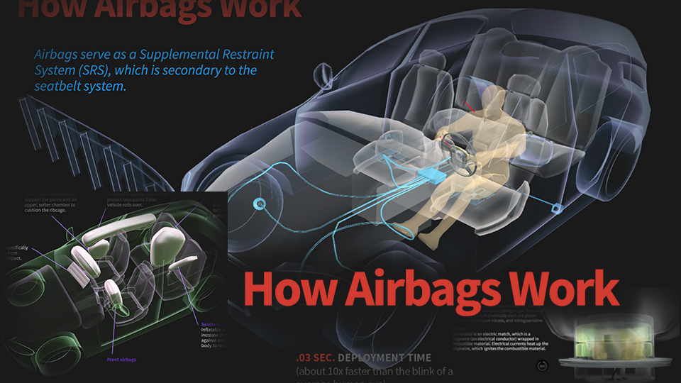
An airbag system is comprised of several key components working in concert:
- Crash Sensors: These are accelerometers strategically placed around the vehicle (typically in the front bumper, side doors, and near the ACU). They measure the rate of deceleration during a collision.
- Airbag Control Unit (ACU): The "brain" of the system. It receives signals from the crash sensors, processes the data, and determines whether airbag deployment is necessary. It also controls the timing and intensity of the deployment.
- Airbag Module: This contains the folded airbag itself and the inflator. The inflator is a chemical propellant that, when ignited, rapidly produces a large volume of gas.
- Clockspring: Located in the steering column, the clockspring allows the steering wheel to rotate while maintaining an electrical connection to the driver's side airbag.
- Wiring Harness: Connects all the components, transmitting signals and power.
- Diagnostic System: Monitors the health of the airbag system and illuminates a warning light on the dashboard if a fault is detected.
How It Works: The Chain Reaction
The process unfolds in milliseconds:
- Impact Detection: Crash sensors detect a sudden deceleration exceeding a pre-defined threshold.
- Signal Transmission: Sensors send signals to the ACU.
- ACU Evaluation: The ACU analyzes the signals, factoring in the severity and direction of the impact. Algorithms determine if airbag deployment is required.
- Ignition Signal: If deployment is deemed necessary, the ACU sends an electrical signal to the inflator within the airbag module.
- Inflator Activation: The electrical signal ignites a chemical propellant (typically sodium azide, which decomposes to produce nitrogen gas).
- Bag Inflation: The rapid production of nitrogen gas inflates the airbag, bursting through the module cover.
- Occupant Cushioning: The inflated airbag provides a cushion, distributing the impact force over a larger area and preventing direct contact with hard surfaces.
- Venting: Once the occupant has made contact, the airbag begins to deflate through vents, preventing rebound injuries.
Symbols and Wiring Diagrams
When working with airbag systems, understanding wiring diagrams and symbols is essential. Here are some common symbols you might encounter:
- Airbag Module: Often depicted as a stylized airbag shape.
- Crash Sensors: Usually represented as small squares or circles with a sensing element symbol inside.
- ACU: A rectangular box with multiple input and output connections.
- Wiring: Lines represent wires. Different colors indicate different functions (e.g., red for power, black for ground, yellow for airbag circuits – a near-universal safety code).
- Connectors: Shown as interlocking shapes, often circles or rectangles.
- Ground: Usually a series of downward-pointing lines.
The line styles also matter. Solid lines typically indicate power or signal wires, while dashed lines might represent grounding connections or shielded cables.
Real-World Use: Basic Troubleshooting
While airbag system repairs are generally best left to qualified professionals, basic troubleshooting can help you identify potential problems.
- Airbag Warning Light: If the airbag warning light illuminates on your dashboard, it indicates a fault within the system. Have it diagnosed by a qualified mechanic. Do not attempt to diagnose or repair the system yourself unless you are properly trained and equipped.
- Loose Connections: Check for loose or corroded connectors, particularly after a minor accident or if you've been working on other electrical systems in the car. Never probe airbag connectors with a multimeter unless you know exactly what you are doing.
- Clockspring Issues: Symptoms can include a non-functioning horn, cruise control problems, or the airbag warning light illuminating when turning the steering wheel. Clockspring replacement requires careful attention to detail and should be performed by someone with experience.
Important Note: Intermittent issues are often the hardest to diagnose. The ACU stores Diagnostic Trouble Codes (DTCs), which can provide clues about the nature of the fault. A professional scan tool is needed to read these codes.
Safety: Handle with Extreme Care
Airbag systems contain potentially dangerous components. The inflator module, in particular, can be hazardous if mishandled. The chemical propellant can detonate unexpectedly, causing serious injury or even death.
- Always disconnect the battery and wait at least 10 minutes before working on any airbag system component. This allows the system's capacitors to discharge, reducing the risk of accidental deployment.
- Never probe airbag connectors with a multimeter unless specifically instructed by a repair manual and you have the proper training.
- Never expose airbag modules to heat, flame, or static electricity.
- Always follow the manufacturer's instructions for handling and disposal of airbag modules.
- If in doubt, seek professional assistance. It's simply not worth risking your safety.
Static electricity is a significant hazard. Ground yourself properly by touching a grounded metal object before handling any airbag components. Work in a static-free environment if possible.
Further Resources and Diagrams
A detailed wiring diagram of your vehicle's airbag system can be incredibly helpful for understanding the connections and troubleshooting potential issues. We have a generic airbag system diagram available for download, which can serve as a useful reference. Keep in mind that specific wiring configurations vary significantly between makes and models, so always consult the factory service manual for your vehicle.
Understanding the speed at which airbags deploy, the components involved, and the associated safety precautions is paramount for anyone working on or around these life-saving systems. While this article provides a foundational understanding, always prioritize safety and seek professional assistance when in doubt. Your safety, and the safety of others, depends on it.