At What Speed To Airbags Deploy
Understanding the deployment speed of airbags is crucial for anyone involved in vehicle repair, modification, or even just wanting a deeper understanding of their car's safety systems. Whether you're diagnosing an SRS (Supplemental Restraint System) fault, planning a modification that might affect sensor placement, or simply satisfying your curiosity, this knowledge provides a solid foundation. Knowing the intricacies of airbag deployment, particularly the speed at which it occurs, allows you to approach diagnostic and repair tasks with a greater awareness of the forces involved and the potential hazards.
Key Specs and Main Parts of an Airbag System
The airbag system isn't a single component but a collection of interconnected parts working in concert. Understanding these parts and their specifications is essential. Here's a breakdown:
- Crash Sensors: These are typically accelerometers, devices that measure rapid changes in velocity. They are strategically placed in the vehicle, usually in the front and sometimes on the sides. The placement is crucial for accurate impact detection. Their sensitivity is a key specification, dictating the minimum deceleration rate required to trigger a signal.
- Airbag Control Module (ACM) or Supplemental Restraint System (SRS) Module: This is the "brain" of the system. It receives signals from the crash sensors, processes the data, and determines if airbag deployment is necessary. It also stores diagnostic trouble codes (DTCs) related to system faults. Its processing speed and the algorithms it uses are critical.
- Airbags: The inflatable cushions themselves, usually made of nylon fabric. Specifications include their volume (in liters), inflation pressure, and deployment angle.
- Inflator: This is the component that rapidly generates gas to inflate the airbag. Modern inflators often use a solid propellant, typically a mixture of sodium azide (NaN3) and other chemicals. Older systems might use compressed gas. The burn rate of the propellant is a critical specification determining inflation speed.
- Clock Spring: A coiled ribbon cable that allows the steering wheel to rotate while maintaining electrical connections to the airbag and other steering wheel-mounted controls.
- Wiring Harness: Connects all the components together. High-quality, shielded wiring is essential to prevent electromagnetic interference.
Understanding System Diagrams: Symbols and Conventions
System diagrams use standardized symbols to represent various components and connections. Here's a brief overview of common symbols:
- Solid lines: Represent electrical wiring. Thicker lines might indicate power cables.
- Dashed lines: Often represent diagnostic communication lines, such as CAN (Controller Area Network) bus connections.
- Boxes: Typically represent electronic modules, like the ACM/SRS module.
- Circles with an "S" inside: Represent crash sensors.
- "Airbag" symbol: A stylized representation of an airbag, often labeled with its location (e.g., Driver Airbag, Passenger Airbag).
- Ground symbol: Indicates a connection to the vehicle's chassis ground.
- Connectors: Represented by various shapes, often with numbers indicating pin assignments.
- Color coding: While not universally standardized, some diagrams use colors to differentiate between different types of signals (e.g., power, ground, signal). Refer to the specific diagram's legend for details.
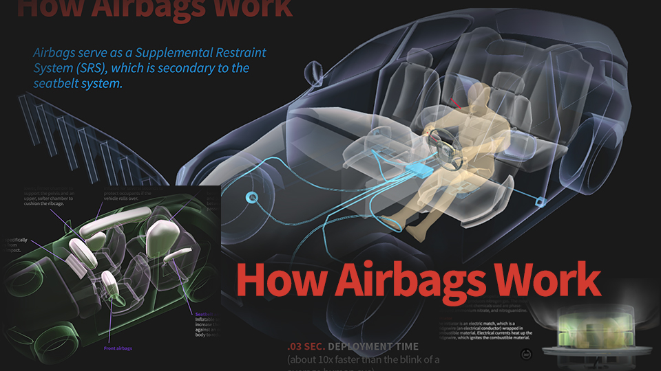
How Airbag Deployment Works: A Step-by-Step Explanation
The airbag deployment process happens incredibly fast, in a matter of milliseconds. Here's a simplified explanation:
- Impact Detection: Crash sensors detect a sudden deceleration exceeding a predefined threshold. This threshold is calibrated to differentiate between normal braking and a collision.
- Signal Transmission: The sensors send signals to the ACM/SRS module.
- Data Processing: The ACM/SRS module analyzes the signals from multiple sensors. It uses sophisticated algorithms to determine the severity of the impact, the direction of the impact, and whether airbag deployment is necessary. This is a crucial step, as deploying airbags unnecessarily can be dangerous.
- Deployment Decision: If the ACM/SRS module determines that airbag deployment is warranted, it sends an electrical signal to the appropriate airbag inflator(s).
- Inflation: The electrical signal ignites the propellant within the inflator. The rapid combustion of the propellant generates a large volume of gas, primarily nitrogen, which inflates the airbag. This entire process, from signal to full inflation, occurs in approximately 30-50 milliseconds. This is faster than the blink of an eye.
- Deflation: The airbag is designed to deflate rapidly after full inflation. This allows the occupant to regain visibility and prevents the airbag from interfering with rescue efforts. The bag deflates through vents designed into the bag.
At What Speed Do Airbags Deploy?: This is where things get interesting. It's not about the vehicle's speed in mph, but rather the change in velocity (deceleration) within a specific timeframe. Think of it as the rate of stopping. A head-on collision at 12-14 mph into a rigid barrier might trigger airbag deployment because the deceleration is extremely rapid. Conversely, a collision at 30 mph into a deformable object (like a car) might not trigger deployment if the deceleration is spread out over a longer time. The key factor is the *delta-v* (change in velocity). Typically, airbags are designed to deploy when the delta-v exceeds a certain threshold within a short period (milliseconds). This threshold is specific to the vehicle model and the sensor's calibration. However, for a frontal impact, a delta-v exceeding approximately 8-12 mph within 20-30 milliseconds is often cited as a general guideline. Side airbags often deploy with even smaller delta-v thresholds due to the reduced crush zone in side impacts.
Real-World Use: Basic Troubleshooting Tips
If the airbag warning light is illuminated on your dashboard, it indicates a fault within the SRS. Here are some basic troubleshooting steps (always disconnect the battery before working on the SRS):
- Scan for Diagnostic Trouble Codes (DTCs): Use an OBD-II scanner that supports SRS diagnostics to retrieve DTCs. These codes will provide clues about the nature of the fault.
- Check Connections: Inspect all wiring connectors related to the SRS, particularly those at the crash sensors, ACM/SRS module, and airbags. Look for corrosion, loose connections, or damaged wiring.
- Inspect the Clock Spring: A faulty clock spring can cause airbag issues and trigger a DTC.
- Consult a Repair Manual: Refer to a vehicle-specific repair manual for detailed troubleshooting procedures and wiring diagrams.
- Sensor testing: Some sensors can be tested using a multimeter to verify its resistance is within specified range when the sensor is NOT under stress. Consult a repair manual.
Important Note: SRS troubleshooting can be complex and potentially dangerous. If you're not comfortable working with electrical systems or have limited experience, it's best to consult a qualified mechanic.
Safety: Highlighting Risky Components
The airbag system contains potentially dangerous components. Mishandling them can result in serious injury or death. Always observe the following safety precautions:
- Disconnect the Battery: Always disconnect the negative battery terminal before working on the SRS. This will prevent accidental airbag deployment.
- Wait for the Backup Power to Dissipate: After disconnecting the battery, wait at least 10 minutes to allow the backup power supply in the ACM/SRS module to discharge. Some manufacturers recommend longer wait times.
- Handle Airbags with Care: Airbags are explosive devices. Handle them gently and avoid dropping or subjecting them to excessive heat.
- Never Probe Airbag Connectors: Probing airbag connectors with a multimeter or test light can trigger deployment.
- Consult a Repair Manual: Always refer to a vehicle-specific repair manual for detailed safety procedures and warnings.
- Proper Disposal: Deployed and undeployed airbags need to be disposed of properly, adhering to local regulations. They are hazardous materials and cannot be simply thrown away.
The knowledge shared here is intended to provide a basic understanding of airbag systems and their deployment characteristics. Always prioritize safety and consult professional resources when performing repairs or modifications.
We have a comprehensive diagram of a typical airbag system available for download, which includes detailed sensor placements, wiring schematics, and component specifications. This resource will further enhance your understanding and aid in troubleshooting. Contact us for the file.