At What Speed Will Airbags Deploy
Understanding airbag deployment speed is crucial for anyone involved in car maintenance, modification, or even accident analysis. Knowing the intricacies of this safety system can inform repair decisions, help diagnose problems, and even contribute to a deeper understanding of vehicle safety design. This article breaks down the technical aspects of airbag deployment speed, providing you with the knowledge to work safely and effectively on vehicles.
Purpose: Why Understanding Airbag Deployment Matters
Imagine you're replacing a damaged bumper after a minor fender-bender. While the airbags didn't deploy, understanding the system's sensitivity and deployment thresholds is vital. Perhaps the impact sensor was stressed, and while not triggered, might be compromised. Knowing the typical deployment speed and the factors influencing it helps you determine if further inspection of the SRS (Supplemental Restraint System) is necessary. Similarly, if you're modifying a vehicle – say, adding a bull bar – you need to understand how that modification might impact the operation of the front impact sensors. This knowledge prevents accidental deployments and ensures the airbag system continues to function as intended.
This information is also important when diagnosing airbag malfunctions. A diagnostic trouble code (DTC) related to an impact sensor might indicate a problem not just with the sensor itself, but also with the deployment threshold. Having a solid understanding of how the system is designed to operate allows you to troubleshoot more effectively.
Key Specs and Main Parts
The airbag system consists of several key components, each contributing to the overall deployment speed and effectiveness:
- Impact Sensors: These are accelerometers strategically placed around the vehicle (typically in the front bumper and side doors) that detect the sudden deceleration associated with a collision.
- Airbag Control Module (ACM) / Supplemental Restraint System (SRS) Module: This is the "brain" of the system. It receives signals from the impact sensors, processes the data, and determines whether or not to deploy the airbags.
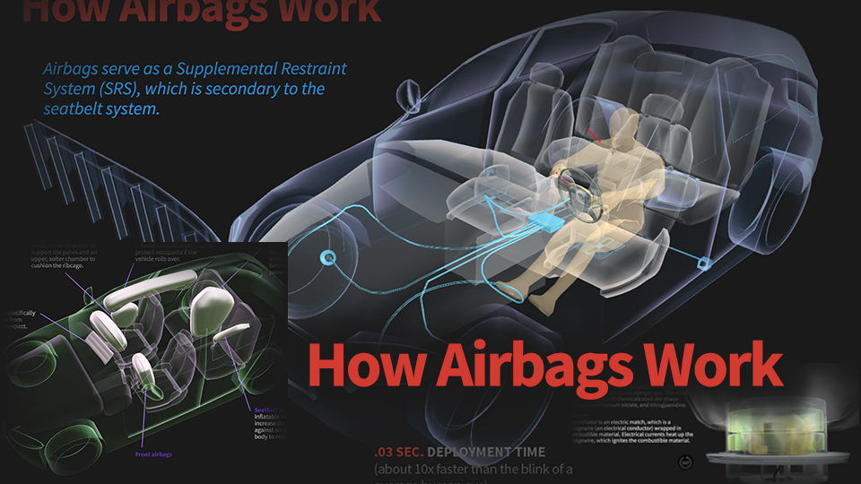
- Airbags: The inflatable cushions designed to protect occupants during a crash. They are housed within the steering wheel, dashboard, and seats.
- Inflators: These devices contain a chemical propellant (historically sodium azide, now often a mixture of guanidine nitrate and other compounds) that, when ignited, produces a large volume of gas very quickly to inflate the airbag.
- Wiring Harness: Connects all the components, ensuring reliable communication.
- Clock Spring: A rotary electrical connector that maintains electrical connection to the airbag in the steering wheel while allowing it to rotate.
Typical Deployment Speed: Airbags are designed to deploy within milliseconds of a collision. A common figure cited is between 30 and 60 milliseconds. However, this deployment time is affected by several factors, which directly impact the equivalent deployment speed. The critical factor is the delta-V (Δv), or change in velocity, experienced by the vehicle during the impact.
While we often talk about "speed", it's more accurate to think of it as an acceleration threshold. The ACM monitors the rate of deceleration. A typical front airbag deployment threshold might be equivalent to a frontal impact at 12-14 mph (20-23 km/h) into a rigid barrier. Side airbags often have lower thresholds, deploying at impacts equivalent to 8-10 mph (13-16 km/h). These speeds are just representative, and the exact figures vary considerably based on the vehicle manufacturer, model, and airbag system design.
Symbols: Understanding Schematics
Airbag system schematics use standard electrical symbols. Here's a breakdown of some common ones:
- Solid Lines: Represent wires connecting components. Thicker lines often indicate power or ground circuits.
- Dashed Lines: May represent diagnostic communication lines, or shielded wiring.
- Connectors: Depicted as interlocking shapes. Each connector is usually labeled with a code identifying its location and pin configuration.
- Impact Sensors: Often represented as a small box with an arrow indicating the direction of sensitivity.
- Airbag Modules: Shown as a rectangle with labels indicating their function (e.g., "ACM," "SRS").
- Ground Symbols: Indicate connection to the vehicle's chassis ground.
- Resistors: Used to provide a specific electrical resistance in the circuit. In airbag systems, they are often used to monitor the integrity of the airbag inflator circuit.
- Capacitors: Used to store electrical charge, often used in filtering circuits.
Color coding is also important. While not universally standardized across all manufacturers, red often signifies power, black indicates ground, and other colors are used for signal wires. Always consult the vehicle-specific wiring diagram for accurate color-coding information.
How It Works
The sequence of events leading to airbag deployment is as follows:
- Impact Detection: Impact sensors detect a sudden change in velocity (deceleration) exceeding a pre-defined threshold.
- Signal Transmission: The sensors send a signal to the ACM.
- Data Processing: The ACM analyzes the signals from multiple sensors, considering factors like impact severity, direction, and seat occupancy status (if equipped with seat occupancy sensors).
- Deployment Decision: If the ACM determines that deployment is necessary, it sends a firing signal to the appropriate inflator(s).
- Inflation: The inflator ignites the propellant, producing a large volume of gas that rapidly inflates the airbag.
- Deployment: The airbag bursts through the cover and inflates in front of the occupant.
- Deflation: The airbag deflates through vent holes, cushioning the occupant's impact and preventing rebound injuries.
The ACM uses sophisticated algorithms to make deployment decisions. It takes into account not only the severity of the impact but also factors such as whether the seatbelts are fastened (if equipped with seatbelt pre-tensioners), the occupant's size and weight (if equipped with advanced airbag systems), and the presence of a child seat. This ensures that the airbags deploy appropriately for the specific circumstances of the crash.
Real-World Use: Basic Troubleshooting Tips
If the airbag warning light is illuminated, it indicates a problem with the SRS. Here are some basic troubleshooting steps:
- Scan for Diagnostic Trouble Codes (DTCs): Use an OBD-II scanner to retrieve any DTCs stored in the ACM. This is the first step in diagnosing the problem.
- Check Connectors: Inspect all airbag system connectors for corrosion, damage, or loose connections. Pay particular attention to connectors near impact sensors and the ACM.
- Inspect Wiring Harnesses: Look for damaged or frayed wiring harnesses. Especially around areas where they could have rubbed against something.
- Check the Clock Spring: If the airbag light came on after steering work, the clock spring could be damaged.
Remember: Airbag systems are complex and potentially dangerous. If you are not comfortable working on electrical systems, it is best to take your vehicle to a qualified technician.
Safety: Risky Components
The airbag inflator is the most dangerous component of the SRS. It contains a potentially explosive propellant. Never attempt to disassemble or tamper with an inflator. Improper handling can lead to accidental deployment, resulting in serious injury or even death.
Before working on any part of the SRS, disconnect the negative battery terminal and wait at least 10 minutes. This allows the capacitors in the ACM to discharge, reducing the risk of accidental deployment. When handling airbags, wear safety glasses and gloves. Always follow the manufacturer's recommended procedures for handling and disposing of airbags.
Always consult the vehicle's service manual for specific safety precautions and procedures. Incorrectly installing an airbag can render it ineffective or even dangerous in the event of a collision.
Airbag systems are a vital safety feature in modern vehicles, and understanding their operation is essential for safe and effective vehicle maintenance and modification. By understanding the principles discussed above, you will be much better equipped to diagnose SRS problems and safely work on your vehicles.
For a detailed schematic diagram of a typical airbag system, including sensor locations and wiring configurations, contact us. We have the file available for download. This detailed diagram will give you an even more granular view of the system and aid in your understanding.