Auto 4wd How Does It Work
Auto 4WD, or Automatic Four-Wheel Drive, is a system designed to automatically engage four-wheel drive when the vehicle detects wheel slippage, offering enhanced traction on slippery or uneven surfaces. Unlike traditional part-time 4WD systems, which require manual engagement, Auto 4WD aims to provide a seamless and convenient driving experience. This article delves into the intricacies of Auto 4WD, exploring its components, operation, troubleshooting, and safety considerations. Understanding how Auto 4WD works is crucial for diagnosing issues, performing maintenance, or even considering modifications. Having a grasp of the system's architecture empowers you to make informed decisions about your vehicle's performance and longevity.
Key Specs and Main Parts
The heart of an Auto 4WD system lies in its ability to detect and react to wheel slippage. Here's a breakdown of the key components and specifications:
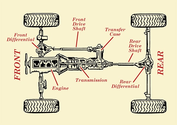
- Transfer Case: The transfer case is the core component that distributes power from the transmission to both the front and rear axles. In Auto 4WD systems, it often incorporates a viscous coupling, electronically controlled clutch, or other mechanism to variably distribute torque. The torque split can range from 100% to the rear wheels (in normal conditions) to a more even distribution (e.g., 50/50) when slippage is detected.
- Wheel Speed Sensors: These sensors, typically integrated with the Anti-lock Braking System (ABS), constantly monitor the rotational speed of each wheel. Discrepancies in wheel speed indicate slippage.
- Electronic Control Unit (ECU): The ECU, sometimes referred to as a Transfer Case Control Module (TCCM), is the brain of the Auto 4WD system. It receives data from the wheel speed sensors and other inputs, such as throttle position and brake application, and determines when and how much to engage the front axle.
- Actuator/Motor: This component physically engages or disengages the front axle. It can be an electric motor, a solenoid, or a vacuum-operated actuator, depending on the specific system design.
- Dashboard Switch/Selector: This allows the driver to select different 4WD modes, often including 2WD (two-wheel drive), Auto 4WD, and sometimes 4HI (four-wheel drive high range) or 4LO (four-wheel drive low range).
- Driveshafts: The front and rear driveshafts transmit power from the transfer case to the respective axles.
- Axles: The front and rear axles contain the differential gears, which allow the wheels on each axle to rotate at different speeds during turns.
Symbols and Lines
Automotive diagrams often use standardized symbols and line conventions to represent different components and connections. Understanding these conventions is crucial for interpreting the diagrams effectively.
- Solid Lines: Typically represent mechanical linkages, fluid lines (e.g., hydraulic), or electrical wiring carrying significant current (e.g., power supply).
- Dashed Lines: Often indicate vacuum lines, signal wires (e.g., from sensors to the ECU), or control lines.
- Circles: Can represent sensors, actuators, or other components. The specific symbol within the circle will indicate the type of component.
- Squares/Rectangles: Commonly used to represent electronic control units (ECUs), relays, or other electrical components.
- Arrows: Indicate the direction of flow (e.g., fluid flow in a hydraulic line) or the direction of movement (e.g., actuator movement).
- Ground Symbol: Represents the electrical ground connection.
- Color Coding: While not always consistent across all manufacturers, color coding can be used to identify different circuits or systems. For example, red wires often indicate power supply, while black wires often indicate ground.
How It Works
The operation of an Auto 4WD system can be broken down into several key steps:
- Monitoring Wheel Speed: The wheel speed sensors continuously monitor the rotational speed of each wheel. These sensors send signals to the ECU.
- Detecting Slippage: The ECU compares the wheel speeds. If one or more wheels are rotating significantly faster than the others, the ECU interprets this as wheel slippage. A predefined threshold determines what constitutes significant slippage.
- Engaging the Front Axle: Upon detecting slippage, the ECU activates the actuator/motor. This actuator engages the front axle, directing power from the transfer case to the front wheels. The method of engagement varies depending on the transfer case design. Some use a viscous coupling, which gradually transfers torque as the fluid inside heats up due to the speed difference. Others use an electronically controlled clutch, which allows for more precise and rapid engagement.
- Torque Distribution: The transfer case dynamically adjusts the torque split between the front and rear axles based on the severity of the slippage. In many systems, the initial torque split is relatively low (e.g., 10% to the front), gradually increasing as needed to maintain traction.
- Disengaging the Front Axle: Once the slippage is no longer detected (i.e., the wheel speeds normalize), the ECU deactivates the actuator, disengaging the front axle and returning the vehicle to two-wheel drive. This transition is often seamless and unnoticeable to the driver.
- Driver Override: The dashboard switch/selector allows the driver to override the automatic function and select other 4WD modes, such as 4HI or 4LO, for specific driving conditions.
Real-World Use and Basic Troubleshooting
Here are some basic troubleshooting tips for Auto 4WD systems:
- Check the 4WD Indicator Light: If the 4WD indicator light is constantly illuminated or flashing, it indicates a problem with the system.
- Listen for Unusual Noises: Grinding, clunking, or whining noises from the transfer case or axles can indicate mechanical issues.
- Inspect Wheel Speed Sensors: Visually inspect the wheel speed sensors and their wiring for damage or corrosion. A faulty wheel speed sensor can trigger false slippage detections.
- Scan for Diagnostic Trouble Codes (DTCs): Use an OBD-II scanner to check for DTCs related to the Auto 4WD system. These codes can provide valuable clues about the nature of the problem. Common codes relate to wheel speed sensor failures, actuator malfunctions, or ECU errors.
- Test Actuator/Motor: Use a multimeter to check the voltage and current to the actuator/motor. A lack of power indicates a wiring issue or a faulty ECU. You can also try manually actuating the motor (if possible) to see if it is functioning correctly.
- Visually Inspect the Transfer Case: Check the transfer case for leaks or damage. Low fluid levels can lead to overheating and premature wear.
Safety Considerations
Working on Auto 4WD systems involves potential risks. Here are some key safety precautions:
- Disconnect the Battery: Before working on any electrical components, disconnect the negative battery terminal to prevent accidental shorts.
- Support the Vehicle Properly: When lifting the vehicle, use jack stands to securely support it. Never work under a vehicle supported only by a jack.
- Be Aware of Rotating Parts: When the engine is running, be extremely cautious of rotating parts such as driveshafts and axles. Keep hands, clothing, and tools clear of these parts.
- High Pressure Fluid: Some systems use hydraulic actuators. Use caution if disconnecting hydraulic lines, as they may be under high pressure.
- Consult the Service Manual: Always refer to the vehicle's service manual for specific instructions and torque specifications.
- The Transfer Case and Driveshafts are heavy! When removing them, use proper lifting techniques and have assistance if needed. Dropping these components can cause serious injury.
- Do not attempt repairs you are not comfortable with. If you are unsure about any aspect of the repair, consult a qualified mechanic.
This article provides a general overview of Auto 4WD systems. Specific designs and features may vary depending on the vehicle manufacturer and model. It's always recommended to consult the vehicle's service manual for detailed information. We have a sample Auto 4WD wiring diagram available for download, which can further aid in your understanding of the system. Please contact us for access to the file. Good luck with your repairs!