Electric Motor How Does It Work
So, you're looking to dive deeper into the inner workings of electric motors? Excellent! Whether you're planning to tinker with your EV, build your own custom electric vehicle, or simply expand your knowledge base, understanding the fundamental principles behind how these motors operate is crucial. This guide will break down the core components, electrical principles, and operational aspects of a typical electric motor, giving you the technical insight you need.
Why Understanding Electric Motors Matters
Let's be honest, electric motors are becoming increasingly prevalent, not just in EVs, but also in countless appliances and tools. Understanding how they function isn't just for academic interest. It empowers you to:
- Diagnose and troubleshoot common motor failures.
- Optimize performance through understanding operating parameters.
- Make informed decisions when selecting motors for specific applications.
- Perform basic repairs and maintenance (within safe limits, of course!).
- Gain a deeper appreciation for the technology driving modern electric vehicles.
Think of it like this: knowing the anatomy of a combustion engine helps you understand how to fix a misfire. Similarly, understanding the inner workings of an electric motor equips you to tackle electrical issues down the road. We even have a detailed diagram of a typical electric motor which you can download at the end of this article.
Key Specs and Main Parts
Electric motors come in many shapes and sizes, but they all share some fundamental components. Here's a breakdown of the key players:
- Stator: The stationary part of the motor. It contains the windings (coils of wire) that create the magnetic field.
- Rotor: The rotating part of the motor. It interacts with the magnetic field produced by the stator, causing it to spin. There are different types of rotors, including squirrel-cage rotors (commonly used in induction motors) and wound rotors (used in some DC motors).
- Windings: Coils of wire that carry the electrical current. The arrangement and number of windings directly impact the motor's torque, speed, and efficiency. The current flowing through the windings creates a magnetic field.
- Commutator (DC motors): A rotating switch that reverses the current flow in the rotor windings, maintaining continuous rotation. This is more commonly found in brushed DC motors.
- Brushes (DC motors): Conductive blocks that make contact with the commutator, transferring electrical current to the rotor windings. These wear down over time and are a common source of failure in brushed DC motors.
- Bearings: Support the rotor and allow it to rotate freely.
- Housing: Protects the internal components from damage and provides a mounting point for the motor.
Key Specs to Consider:
- Voltage (V): The electrical potential required to operate the motor.
- Current (A): The amount of electrical current the motor draws.
- Power (W or HP): The rate at which the motor performs work. (Watts = Volts x Amps)
- Speed (RPM): Rotations per minute – how fast the motor spins.
- Torque (Nm or lb-ft): The twisting force the motor can produce. Higher torque means the motor can handle heavier loads.
- Efficiency (%): The percentage of electrical power converted into mechanical power. A higher efficiency rating means less energy is wasted as heat.
Understanding Electrical Symbols
When examining electrical diagrams of motor circuits, you'll encounter specific symbols. Here's a quick cheat sheet:
- Lines: Represent electrical conductors (wires). Thicker lines often indicate higher current-carrying capacity.
- Circles with "M" inside: Represents the electric motor itself.
- Coils (squiggly lines): Represents inductors or windings.
- Resistors (zigzag lines): Represents components that impede current flow.
- Capacitors (two parallel lines): Represents components that store electrical energy.
- Switches (lines with a break): Represents components that control the flow of current.
- Ground Symbol (stacked horizontal lines): Represents a connection to ground (zero potential). This is important for safety.
Color Coding: While not always standardized, common color codes are used for wiring:
- Black: Typically represents ground or neutral.
- Red: Typically represents a positive voltage or "hot" wire.
- Blue/Yellow/Green: Often used for signal wires or other specific functions. Always consult the diagram specific to your motor/application.
How It Works: The Core Principles
The fundamental principle behind all electric motors is electromagnetism. A current-carrying conductor placed in a magnetic field experiences a force. This force is what makes the motor spin. Here's a simplified breakdown:
- Creating the Magnetic Field: When an electrical current flows through the stator windings, a magnetic field is generated. The strength and direction of this field are determined by the amount of current and the arrangement of the windings.
- Interaction with the Rotor: The rotor (which also contains conductors) is placed within this magnetic field. The interaction between the stator's magnetic field and the rotor's conductors creates a force (Lorentz force) on the rotor.
- Generating Torque: This force is applied at a distance from the rotor's axis of rotation, creating torque – a twisting force.
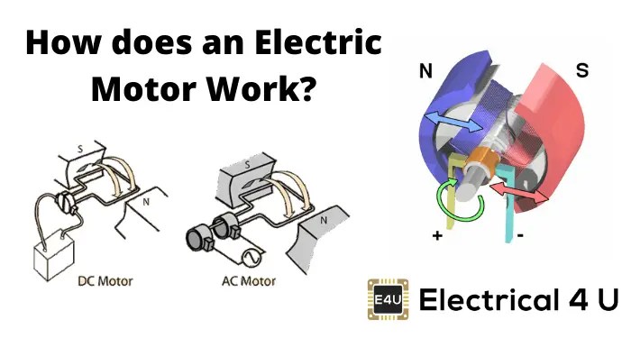
- Continuous Rotation: To maintain continuous rotation, the direction of the force needs to be constantly adjusted. In DC motors, this is achieved by the commutator and brushes, which reverse the current flow in the rotor windings. In AC motors, the alternating current inherently changes the magnetic field, creating rotation.
Simplified Analogy: Imagine pushing a swing. To keep the swing moving, you need to push it in the right direction at the right time. The stator is like your hand, providing the push (magnetic force), and the rotor is like the swing. The commutator (in a DC motor) is like your timing, ensuring you push at the optimal moment to maintain the swing's motion.
Real-World Use: Basic Troubleshooting Tips
Let's say your electric motor isn't working. Where do you start?
- Check the Power Supply: Is the motor receiving the correct voltage? Use a multimeter to verify the voltage at the motor terminals.
- Inspect the Wiring: Look for loose connections, damaged wires, or corroded terminals.
- Listen for Unusual Noises: Grinding, squealing, or clicking sounds can indicate bearing failure or other mechanical problems.
- Check for Overheating: Excessive heat can indicate overloading, short circuits, or poor ventilation.
- Test the Motor Windings (with a multimeter): You can check for short circuits or open circuits in the windings. A healthy winding should have a low resistance value.
Example: A common issue is a worn-out brush in a DC motor. If the motor is weak or not spinning, inspect the brushes. If they are worn down significantly, replacing them might solve the problem.
Safety: Highlighting Risky Components
Working with electric motors involves inherent risks, especially with high-voltage systems. Always prioritize safety.
- High Voltage: Electric motors can operate at dangerously high voltages. Always disconnect the power source before working on the motor. Even after disconnecting, capacitors can store a charge. Discharge them safely before touching any components.
- Moving Parts: The rotating components of the motor can cause serious injury. Ensure the motor is completely stopped and locked out before performing any maintenance.
- Electrical Shock: Contact with live wires can be fatal. Use insulated tools and wear appropriate personal protective equipment (PPE), such as gloves and eye protection.
- Arc Flash: In high-power circuits, a short circuit can create an arc flash, which is an explosive release of energy. Be aware of the potential for arc flash and take necessary precautions, such as wearing arc-rated clothing.
Important Note: If you're uncomfortable working with electrical circuits, consult a qualified electrician. Don't risk your safety for a repair you're unsure about. Electric motors in EVs, in particular, operate at very high voltages and should only be serviced by trained professionals.
You now have a solid foundation in understanding how electric motors work. Remember that this is a simplified overview. There are many different types of electric motors, each with its own unique characteristics. This knowledge will empower you to tackle basic troubleshooting and maintenance tasks, and make informed decisions when working with electric motor systems.
Ready to dive even deeper? As promised, we have a detailed diagram of a typical electric motor available for download. It's a great resource for visualizing the components and their relationships, and a valuable asset for any DIY mechanic or enthusiast.
Click here to download the Electric Motor Diagram: [Link to Diagram Here - Replace with Actual Link]