How Do Electric Car Engines Work
So, you're ready to delve into the heart of an electric vehicle (EV) and understand how that silent, torquey motor spins the wheels? Excellent! Whether you're looking to do some DIY maintenance, understand the intricacies of EV technology, or even consider an electric conversion project, knowing how the electric motor works is fundamental. This article breaks down the inner workings, focusing on clarity and practical understanding for experienced DIYers like yourself.
Why This Matters: Unlocking the Secrets of Electric Drivetrains
Understanding the electric motor isn't just about intellectual curiosity. It empowers you to:
- Troubleshoot basic EV issues (e.g., diagnosing range problems, understanding motor performance).
- Perform preventative maintenance (e.g., understanding cooling system needs, checking for wear and tear).
- Modify EVs responsibly (e.g., considering motor upgrades, optimizing performance within safe limits).
- Convert a gasoline car to electric (a challenging but rewarding project that requires in-depth motor knowledge).
Think of this as a crash course in EV motor mechanics, geared towards someone who isn't afraid to get their hands dirty.
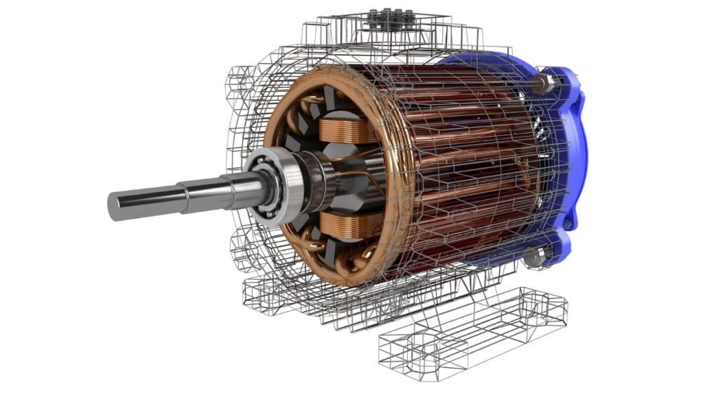
Key Specs and Main Parts: The Anatomy of an Electric Motor
Let's begin by identifying the core components. We'll focus on Permanent Magnet Synchronous Motors (PMSMs) as they're the most common type in modern EVs, known for their efficiency and power density. Other motor types such as Induction motors are used in EVs, but the PMSM is the prevailing design. We'll cover:
- Stator: The stationary part of the motor. It's made up of laminated steel and contains windings of copper wire. These windings are arranged to create a rotating magnetic field when energized. The stator specifications determine the motor's voltage and current ratings, influencing its power output.
- Rotor: The rotating part of the motor, connected to the output shaft that drives the wheels. In a PMSM, the rotor contains permanent magnets. The arrangement and strength of these magnets greatly affect the motor's torque characteristics.
- Inverter: This crucial electronic component converts the DC (Direct Current) electricity from the battery into AC (Alternating Current) electricity needed to power the stator windings. The inverter controls the frequency and amplitude of the AC current, effectively controlling the motor's speed and torque. Think of it as the throttle pedal's brain.
- Resolver/Encoder: A sensor that provides feedback to the inverter about the rotor's position. This is crucial for precise control of the motor. The inverter needs to know the exact position of the rotor to synchronize the AC current correctly. Without this feedback, the motor cannot operate efficiently or reliably.
- Cooling System: Electric motors generate heat, especially under heavy load. Effective cooling, typically liquid-based, is vital to prevent overheating and ensure long motor life. Components include a coolant pump, radiator, and cooling channels within the motor housing.
- Gearbox (Reduction Gear): EVs typically use a single-speed gearbox to reduce the high rotational speed of the motor to a more suitable speed for the wheels. This provides the necessary torque for acceleration and hill climbing.
Symbols: Decoding the Diagram
While this article doesn't come with a traditional schematic diagram directly embedded (think of it as a narrative explanation of one), understanding common electrical symbols is vital. Here are some key concepts:
- Lines: Represent wires. Thicker lines usually indicate higher current carrying capacity. Dashed lines may represent data communication links (e.g., CAN bus).
- Colors: Standard wire colors (e.g., red for positive, black for negative) help identify polarity. In high-voltage EV systems, orange is often used to denote high-voltage circuits.
- Icons: Resistors, capacitors, diodes, transistors, and other electronic components have specific schematic symbols. Knowing these symbols is key to understanding the inverter circuit.
Since we do not have a visual schematic here, think of the inverter in your minds eye as an "H-Bridge" which uses fast acting transistors called MOSFETs to switch power to the motor windings. Knowing the symbols of those components would be key to understanding any electrical drawings.
How It Works: The Dance of Electricity and Magnetism
Here’s the step-by-step breakdown of the PMSM operation:
- Power Flow: The high-voltage battery (typically 300-400V DC) provides the energy.
- Inverter Magic: The inverter converts the DC power to AC power. The inverter rapidly switches the current flow using Insulated Gate Bipolar Transistors (IGBTs) or MOSFETs to create a three-phase AC current. This is a key function!
- Stator Excitation: The AC current flows through the stator windings, creating a rotating magnetic field. The frequency of the AC current determines the speed of the rotating magnetic field.
- Rotor Rotation: The permanent magnets on the rotor are attracted to the rotating magnetic field created by the stator. The rotor “chases” the rotating magnetic field, causing it to spin. Because the rotor's rotation is *synchronized* with the rotating magnetic field of the stator (hence "Synchronous" in PMSM), precise control is possible.
- Torque and Speed Control: The inverter precisely controls the frequency and amplitude of the AC current. Increasing the frequency increases the motor's speed. Increasing the amplitude (current) increases the motor's torque.
- Feedback Loop: The resolver/encoder provides feedback to the inverter about the rotor's position. This allows the inverter to precisely synchronize the AC current with the rotor's position, ensuring optimal torque and efficiency.
- Gearbox: The spinning rotor turns the output shaft, which is connected to a gearbox (reduction gear). The gearbox reduces the high rotational speed of the motor to a more suitable speed for the wheels, increasing torque.
Essentially, the inverter is orchestrating a precise electromagnetic dance between the stator and rotor, turning electrical energy into rotational mechanical energy.
Real-World Use: Basic Troubleshooting Tips
While deep diagnostics require specialized tools, here are some basic troubleshooting tips you can use:
- Reduced Range: Could indicate battery degradation, but also inefficient motor operation. Check for excessive motor heating, which can indicate winding shorts or bearing problems.
- Motor Noise: Unusual whining, clicking, or grinding noises can indicate bearing failure or other mechanical issues within the motor or gearbox.
- Performance Issues: Reduced acceleration or top speed could be due to inverter problems or issues with the resolver/encoder. Consult diagnostic codes (requires an OBD-II scanner compatible with EVs).
- Overheating: Check the coolant level and condition. Ensure the cooling pump is functioning correctly. Blocked cooling channels can also cause overheating.
Important: EV motors and inverters operate at very high voltages. Always disconnect the high-voltage battery before attempting any repairs or maintenance.
Safety: High-Voltage Hazards
This cannot be overstated: EVs contain lethal voltages.
- High-Voltage Components: The battery, inverter, and motor operate at hundreds of volts. Contact with these components can be fatal.
- Safety Precautions: Always disconnect the high-voltage battery following the manufacturer's procedure. Wear appropriate personal protective equipment (PPE), including high-voltage gloves and insulated tools.
- Qualified Technicians: If you are not comfortable working with high-voltage systems, leave repairs to qualified EV technicians.
Discharging a high voltage capacitor inside the inverter after disconnecting the battery can still present a shock hazard. Always follow proper safety procedures!
Remember, safety first! Even experienced DIYers should carefully consider their comfort level and the potential risks before tackling EV motor-related projects.
We have a detailed schematic diagram for further study. You can download the complete diagram of a PMSM motor and inverter circuit to further improve your skills.