How Do You Charge Electric Cars
So, you're diving into the world of electric vehicles (EVs) – fantastic! Whether you're considering converting a classic car, building your own home charging station, or just want to understand what's happening behind that charge port, understanding how EVs charge is crucial. This article breaks down the charging process, focusing on the key components and principles. We'll cover everything from the basic AC/DC conversion to the more complex communication protocols between the car and the charger. And remember, we have a detailed schematic diagram of a typical EV charging system available for download; it's an invaluable resource for repairs, modifications, and deep-dive learning.
Why Understand EV Charging?
Let's be clear: messing with high-voltage systems is dangerous. This information is not a substitute for professional training. However, understanding the fundamentals allows you to:
- Troubleshoot common charging issues: Is your car not charging at the expected rate? Is it refusing to charge altogether? Understanding the system can help you narrow down the problem.
- Plan home charging upgrades intelligently: Knowing the power requirements and circuit specifications ensures you choose the right equipment.
- Safely modify or repair components (with proper training and precautions): While we strongly advise against untrained individuals tampering with high-voltage systems, a solid understanding of the system is essential for qualified technicians.
- Become a more informed EV owner: Understanding the technology empowers you to make better decisions about charging infrastructure and energy consumption.
Key Specs and Main Parts
The EV charging system is more than just a plug and a cable. It involves several crucial components working in concert:
- AC Power Source (Grid): This is where it all starts – the alternating current (AC) electricity from your home or public grid. In North America, this is typically 120V or 240V.
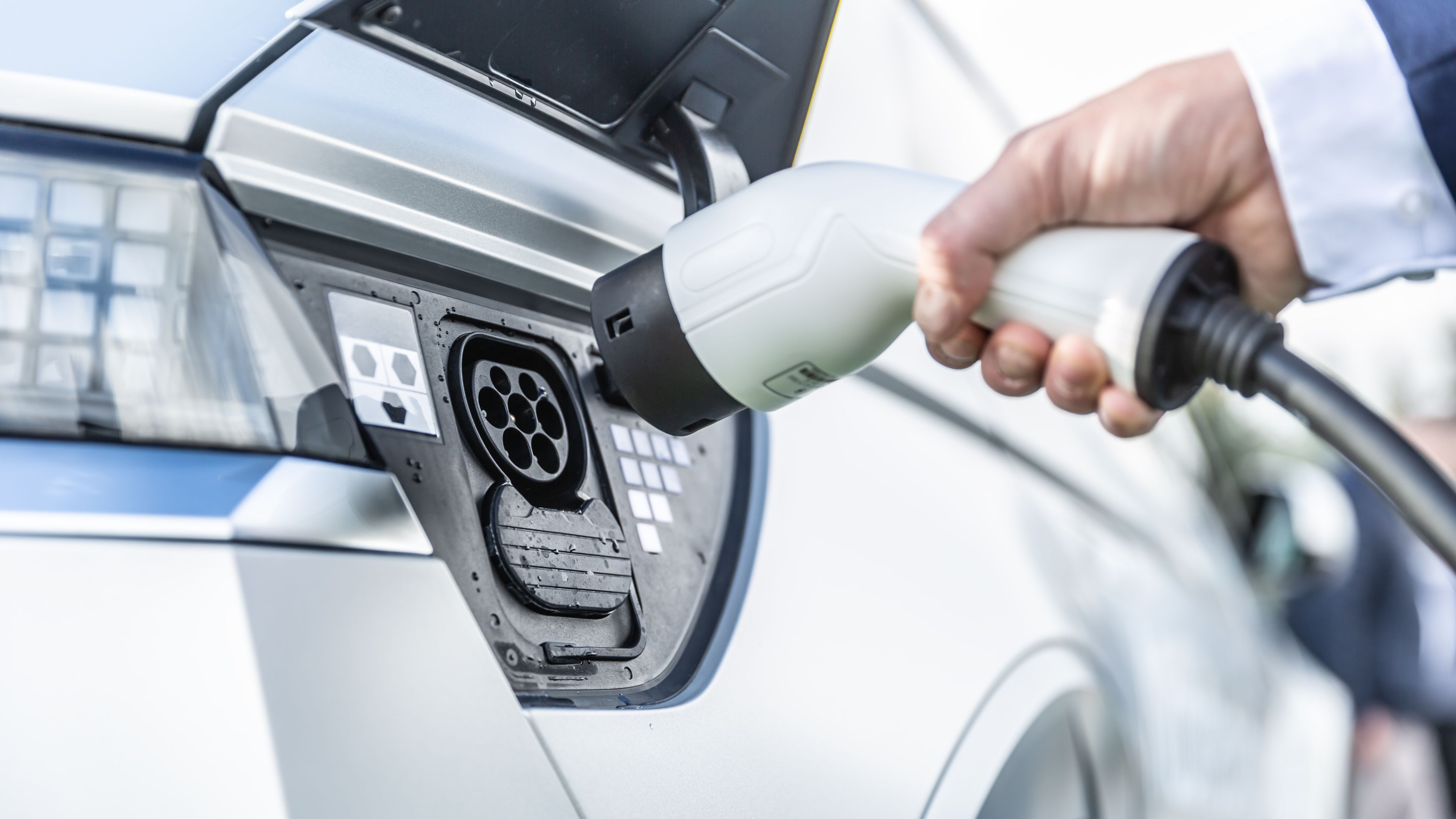
- Charging Port (Inlet): The physical connection point on your car. Common standards include J1772 (Type 1) for Level 1 and Level 2 charging in North America, and CCS (Combined Charging System) which adds DC fast charging capability. In Europe, Type 2 (Mennekes) is prevalent for AC charging, and CCS Type 2 for DC charging.
- Onboard Charger (OBC): This is the AC/DC converter inside your car. It takes the AC power from the charging port and converts it to direct current (DC) to charge the battery. The OBC's power rating (in kW) determines the maximum AC charging speed.
- Battery Management System (BMS): The BMS monitors the battery's voltage, current, temperature, and state of charge (SoC). It communicates with the OBC to regulate the charging process and prevent overcharging or overheating. Think of it as the brain and guardian of the battery.
- High-Voltage Battery Pack: This is the heart of the EV, storing the electrical energy that powers the motor. Battery voltage is typically in the range of 200V to 800V DC, depending on the vehicle.
- DC Fast Charger (External): For rapid charging, EVs can use external DC fast chargers. These chargers bypass the OBC and directly deliver DC power to the battery. Common standards include CHAdeMO (older), CCS, and Tesla's Supercharger network. Power levels can range from 50kW to 350kW or more.
- Charging Station (EVSE): The Electric Vehicle Supply Equipment (EVSE) provides a safe and controlled connection to the grid. It communicates with the car to initiate and manage the charging process. For Level 1 charging, this might be a simple cord with a J1772 connector. For Level 2 and DC fast charging, it's a more complex unit with safety features and communication protocols.
Understanding the Symbols in the Diagram
The diagram (which you can download) uses standard electrical symbols. Here's a quick guide:
- Solid Lines: Represent electrical conductors (wires). Line thickness may indicate current carrying capacity.
- Dashed Lines: Typically indicate communication lines or control signals.
- Ground Symbol: Represents the connection to earth ground for safety. Crucial for preventing electrical shock.
- Resistors: Represented by a zig-zag line.
- Capacitors: Represented by two parallel lines.
- Diodes: Represented by a triangle pointing to a line. Indicates one-way current flow.
- AC Source: Represented by a sine wave inside a circle.
- DC Source: Represented by a positive (+) and negative (-) symbol.
- Connectors: Shown as circles or boxes where wires connect. The J1772 connector, for instance, has specific pins for power, ground, proximity detection, and control pilot signals.
- Colors: Typically, Black represents neutral (in AC systems), Red represents live/hot, and Green or Green/Yellow represents ground. However, always confirm with local electrical codes.
How It Works: The Charging Process
The charging process varies depending on the charging level:
Level 1 Charging (120V AC)
This is the simplest method, using a standard household outlet. The EVSE is usually a simple cord with a J1772 connector. The AC power goes to the OBC, which converts it to DC and charges the battery. Level 1 charging is slow, adding only a few miles of range per hour. This is because the current draw is limited to typically 12 amps. Therefore power is Voltage (120V) * Current (12A) = 1.4kW.
Level 2 Charging (240V AC)
Level 2 charging uses a higher voltage (240V in North America) and a dedicated circuit. The EVSE is a wall-mounted unit that provides a safer and more efficient connection. The charging process is similar to Level 1, but the higher voltage and current (typically 16A to 80A) allow for much faster charging rates. The AC power goes to the OBC, which converts it to DC and charges the battery. Again, power is Voltage (240V) * Current (up to 80A) = 19.2kW, the current is limited by both the EVSE and the onboard charger.
DC Fast Charging
DC fast charging bypasses the OBC entirely. The DC fast charger directly delivers DC power to the battery at high voltage and current. The BMS communicates with the charger to control the charging process and prevent damage to the battery. DC fast charging can add significant range in a short amount of time. This type of charging is where power is typically above 50kW and continues to rise as technology improves.
Regardless of the level, the EVSE and the car communicate using a control pilot signal (CP). This signal indicates the charging current capacity of the EVSE and allows the car to adjust its charging rate accordingly. A proximity detection (PP) signal indicates that the charging cable is properly connected.
Real-World Use: Basic Troubleshooting
Here are a few basic troubleshooting tips, keeping in mind the safety warnings below:
- Car won't charge: Check the charging cable for damage. Verify that the outlet or charging station is working. Ensure the car is not in a fault state (check the dashboard for error messages). Try a different charging station if possible.
- Slow charging: The charging rate is limited by the weakest link in the system. This could be the charging station's power output, the car's OBC capacity, or the battery's charging limitations (especially at high states of charge). Check the specifications of each component.
- Charging interrupted: This could be due to overheating, overcurrent, or a communication error. The BMS will usually stop charging to protect the battery. Check for any error messages on the car's display or the charging station.
Safety First!
Working with EV charging systems involves high voltages and currents. Here's what you absolutely need to know:
- Disconnect Power: Always disconnect the power source before working on any electrical components. This means turning off the breaker at the circuit panel.
- Use Proper PPE: Wear insulated gloves, safety glasses, and appropriate clothing.
- High-Voltage Components: Be extremely careful around the battery pack, OBC, and DC fast charger. These components can carry lethal voltages.
- Qualified Personnel: Unless you are a qualified electrician or EV technician, do not attempt to repair or modify high-voltage components.
- Capacitor Discharge: High-voltage capacitors can store a dangerous charge even after the power is disconnected. They must be properly discharged before working on the circuit. This usually involves using a special discharge tool.
- Lockout/Tagout: Implement lockout/tagout procedures to prevent accidental energization of the circuit.
- Double-Check: Always double-check your work before restoring power.
Understanding EV charging is an exciting journey, and with this information and our downloadable diagram, you're well on your way. Remember to prioritize safety and seek professional assistance when needed. Happy charging!
We have the full schematic diagram available for download. This diagram provides a detailed view of a typical EV charging system, including the wiring, components, and communication protocols. It's a valuable resource for anyone looking to deepen their understanding of EV charging technology. Contact us to receive the download link.