How Do You Use A Remote Start
Alright, let's dive into the fascinating world of remote start systems. Whether you're looking to install one, troubleshoot an existing setup, or just understand how your car magically warms up on a frigid morning, this deep dive will give you the technical know-how. Think of me as your trusted mechanic, laying it all out in a way that makes sense, even if you're not an electrical engineer. We'll cover everything from the core components to basic troubleshooting, all with an eye towards safety.
Purpose
Understanding the remote start system's operation, and particularly having access to a detailed wiring diagram, is crucial for several reasons:
- DIY Installation/Upgrades: Planning to add a remote start system to your vehicle or upgrading an existing one? The diagram is your roadmap.
- Troubleshooting: Is your remote start failing intermittently? A diagram helps you trace signals and pinpoint the faulty component.
- Repairs: Got a burned-out relay or a cut wire? Knowing what goes where is half the battle.
- Customization: Modifying the system for added features (like integration with aftermarket alarms) requires a solid understanding of the wiring.
- Learning: Simply wanting to understand how this technology works is a valid reason. Knowledge is power!
Key Specs and Main Parts
A typical remote start system, regardless of manufacturer, consists of these core components:
- Remote Control/Fob: This is your primary interface, transmitting radio frequency (RF) signals to the receiver. Key specs here include the operating frequency (e.g., 433MHz, 900MHz) and range. Two-way remotes also receive confirmation signals from the vehicle.
- Receiver/Control Module: This is the brains of the operation. It receives the RF signal from the remote, decodes it, and initiates the starting sequence. Key specs include voltage requirements (usually 12V DC), current draw, and the number of programmable outputs.
- Hood Switch: A critical safety feature that prevents the engine from starting if the hood is open. This is usually a simple normally-closed (NC) switch.
- Brake Switch: Another safety feature. Pressing the brake pedal while the engine is running via remote start will typically shut it down. This is usually a normally-open (NO) switch.
- Tachometer Wire (or equivalent): The control module needs to know the engine is running. This can be achieved by monitoring the tachometer signal (RPMs), voltage fluctuations in the charging system, or, in newer vehicles, communication over the CAN bus.
- Ignition Wires: These are the wires that would normally be engaged by the ignition switch. Typical wires include:
- Ignition 1 & 2: Supplies power to the ignition system during cranking and running.
- Accessory: Powers accessories like the radio and climate control.
- Start: Engages the starter motor.
- Neutral Safety Switch Input: For vehicles with automatic transmissions, this ensures the car is in Park or Neutral before remote start is allowed.
- Bypass Module (Immobilizer Bypass): On modern vehicles with immobilizers, a bypass module is required to temporarily disable the immobilizer during the remote start sequence. The immobilizer is an anti-theft system that prevents the engine from starting without the correct key or transponder. This module is often vehicle-specific and requires programming.
Symbols
Understanding the symbols on a wiring diagram is fundamental. Here are some common ones you'll encounter:
- Solid Lines: Represent wires. Thicker lines may indicate higher current-carrying capacity.
- Dashed Lines: Often indicate connections to optional features or signals that are not always present.
- Colors: Wires are often color-coded in the diagram to match the actual wire colors in the vehicle. Common colors include Red (power), Black (ground), Blue, Green, Yellow, and White. Always double-check with a multimeter to confirm wire identity.
- Grounded Symbols: Represent connections to the vehicle's chassis ground.
- Resistor Symbols: Represent resistors, components that limit current flow. Their values are usually indicated in ohms (Ω).
- Capacitor Symbols: Represent capacitors, components that store electrical energy. Their values are usually indicated in farads (F).
- Diode Symbols: Represent diodes, components that allow current to flow in only one direction.
- Relay Symbols: Represent relays, electromagnetic switches that control high-current circuits using a low-current signal.
- Connector Symbols: Show where wires are connected using plugs or connectors.
- Fuse Symbols: Represent fuses, safety devices that protect circuits from overcurrent. The fuse rating (in amps) is usually indicated.
Example: A red solid line might represent a 12V power wire running from the battery, fused at 20 amps, to the remote start module. A dashed blue line might represent a tachometer signal wire that is only used in certain vehicle models.
How It Works
The remote start system works in a specific sequence:
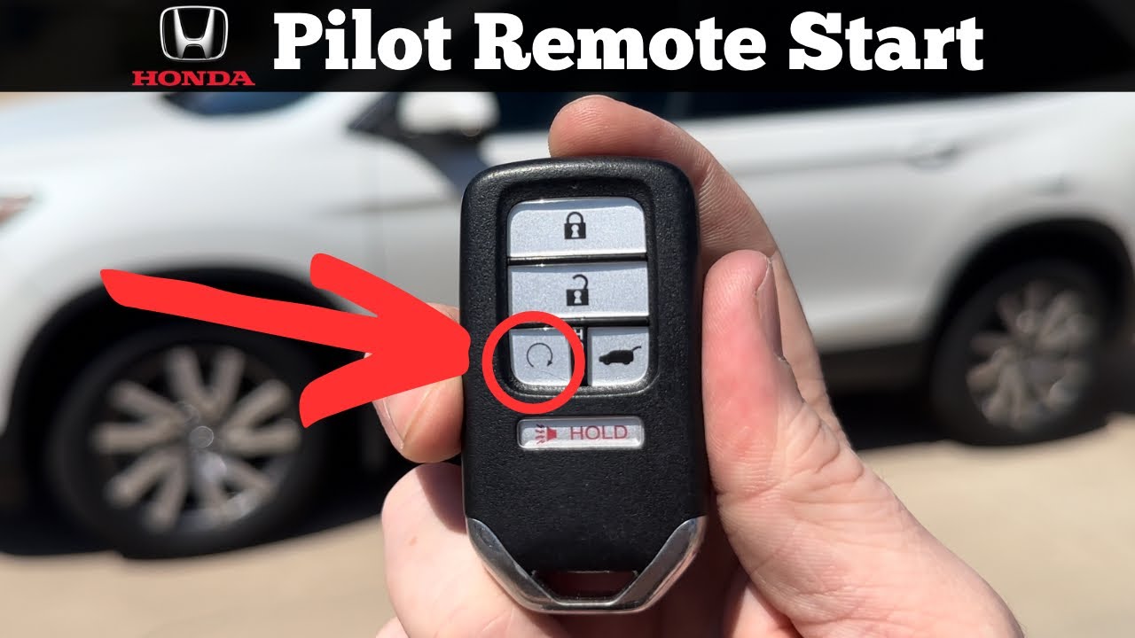
- Remote Activation: You press the start button on the remote.
- Signal Transmission: The remote transmits an RF signal to the receiver/control module in the vehicle.
- Signal Reception and Validation: The control module receives the signal and verifies its authenticity. It checks that the hood switch is closed (hood is down) and, for automatic transmissions, that the neutral safety switch indicates the car is in Park or Neutral.
- Immobilizer Bypass: If the vehicle has an immobilizer, the bypass module is activated to temporarily disable it.
- Ignition Activation: The control module energizes the appropriate ignition wires (Ignition 1, Ignition 2, Accessory, and Start) in the correct sequence to simulate turning the key in the ignition.
- Engine Start: The starter motor engages, cranking the engine until it starts.
- Engine Running Confirmation: The control module monitors the tachometer signal (or charging system voltage) to confirm that the engine is running.
- Run Time: The engine runs for a pre-programmed duration (e.g., 15 minutes).
- Shutdown: The engine shuts down automatically after the run time expires, or if the brake pedal is pressed (if equipped with a brake shutdown feature).
Real-World Use – Basic Troubleshooting Tips
Here are some common problems and how to diagnose them using your newfound knowledge and, crucially, the wiring diagram:
- Remote start doesn't work at all:
- Check the remote's batteries. Obvious, but often overlooked.
- Check the fuses in the remote start module's power supply circuit.
- Verify that the hood switch is properly connected and functioning. A faulty hood switch is a common culprit. Use a multimeter to test for continuity when the hood is closed.
- Check the antenna connection to the receiver module. A loose connection can significantly reduce range.
- Remote start cranks the engine but doesn't start:
- Verify the tachometer signal wire is properly connected and reading correctly. Some modules require programming to learn the tach signal.
- Check the immobilizer bypass module. It may not be functioning correctly. This often requires reprogramming or replacement.
- Ensure that all the necessary ignition wires (Ignition 1, Ignition 2, Accessory) are properly connected to the correct wires in the vehicle's ignition harness. Refer to the wiring diagram!
- Remote start starts the engine, but it shuts off immediately:
- This could be a sign of a weak or incorrect tachometer signal.
- It could also indicate a problem with the immobilizer bypass module.
- Reduced Remote Range:
- Obstructions between the remote and receiver.
- Weak Remote Batteries.
- Antenna placement. Relocate the antenna.
Important: Always use a multimeter to test for voltage and continuity before cutting or connecting any wires. Don't rely solely on wire colors, as they can vary. A wiring diagram from a trusted source will save you a lot of headache and potential damage to your vehicle's electrical system.
Safety – Highlight Risky Components
Working with automotive electrical systems can be dangerous. Here are some safety precautions:
- Disconnect the Battery: Always disconnect the negative terminal of the battery before working on any electrical components. This prevents accidental short circuits and potential shocks.
- Airbags: Be extremely careful when working near airbags. Accidental deployment can cause serious injury. Refer to your vehicle's service manual for specific instructions on disabling the airbag system.
- High-Current Wires: The wires connected to the starter motor and the main power supply are high-current wires. Avoid shorting these wires to ground, as it can cause sparks, fires, and damage to the electrical system.
- Immobilizer Bypass: Incorrect installation or programming of the immobilizer bypass module can compromise your vehicle's security. Always follow the manufacturer's instructions carefully.
- Professional Help: If you are not comfortable working with electrical systems or are unsure about any aspect of the installation, seek professional help. A qualified installer can ensure that the system is installed correctly and safely.
Warning: Tampering with your vehicle's electrical system can void your warranty. Be sure to check your warranty terms before making any modifications.
By understanding the components, how they work, and following safety precautions, you're well on your way to mastering the remote start system. Remember to double-check all connections, use a multimeter to verify voltages and continuity, and always prioritize safety.
We have a generic wiring diagram file available. It provides a visual representation of the connections discussed above. You can download it to aid your installation, troubleshooting, or general understanding of remote start systems.