How Does A Electric Engine Work
So, you're looking to dive deeper into the heart of your electric vehicle, huh? Excellent! Understanding the electric motor is crucial for anyone serious about EV maintenance, modification, or even just plain understanding how your ride works. This article will break down the core principles and components, giving you a solid foundation for tackling more complex EV projects. We’ll even touch on some basic troubleshooting and safety precautions. Plus, we’ve got a detailed schematic available for download that you can refer to. Let's get started!
Purpose: Why Understanding the EV Motor Matters
Why bother learning about the intricacies of an electric motor? Well, for starters, it's the heart of your EV. It's what converts electrical energy into the mechanical motion that gets you from point A to point B. A deeper understanding will empower you to:
- Diagnose problems: Identify potential issues before they become major headaches. Is your efficiency dropping? Is there an unusual noise? Knowing the motor's components can help pinpoint the source.
- Perform basic maintenance: While electric motors are generally low-maintenance, understanding their design can guide preventative measures and identify wear and tear.
- Upgrade and modify: Want to increase performance? Understanding the motor's limitations and capabilities is crucial for safe and effective modifications.
- Appreciate the technology: Gain a deeper understanding of the innovative technology powering your EV and impress your friends with your newfound knowledge!
Key Specs and Main Parts
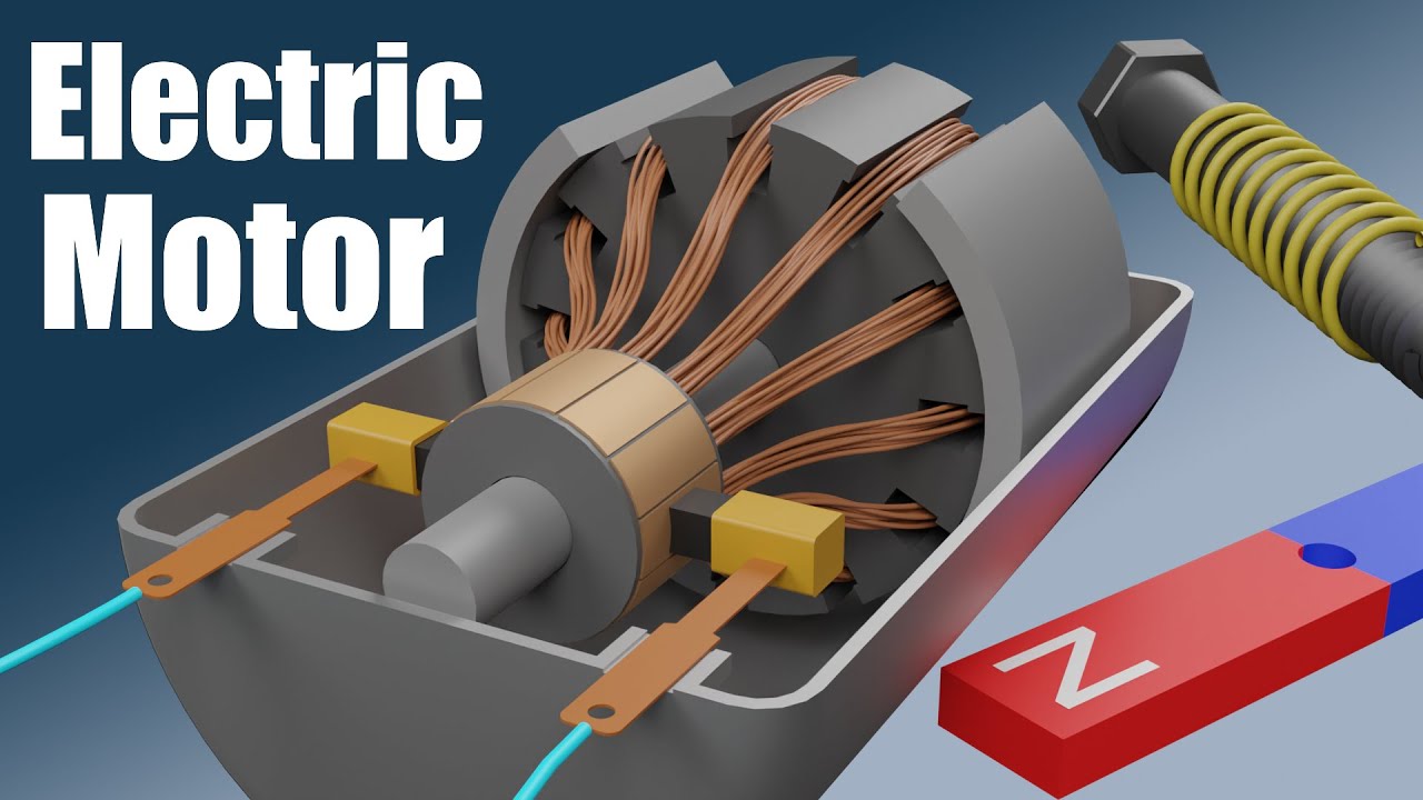
Let's start with the building blocks. While there are different types of electric motors used in EVs (like Permanent Magnet Synchronous Motors - PMSM, Induction Motors, and Switched Reluctance Motors), we'll focus on the widely used PMSM for this explanation. Here's a breakdown of the key parts:
- Stator: The stationary part of the motor. It contains windings of copper wire that create a rotating magnetic field when energized. Think of it as the brain of the motor, directing the action.
- Rotor: The rotating part of the motor. In a PMSM, the rotor has permanent magnets embedded within it. These magnets interact with the magnetic field created by the stator, causing the rotor to spin.
- Windings (Coils): Copper wires wrapped around the stator core. When electricity flows through these windings, they generate a magnetic field. The arrangement and number of windings dictate the motor's torque and speed characteristics.
- Permanent Magnets: Embedded within the rotor, these provide a constant magnetic field. The strength of these magnets is a key factor in the motor's performance.
- Inverter: This crucial component converts DC power from the battery into AC power for the motor. It controls the frequency and voltage of the AC power, which in turn controls the motor's speed and torque.
- Resolver/Encoder: A sensor that provides feedback on the rotor's position and speed. This information is critical for the inverter to precisely control the motor.
- Cooling System: Electric motors generate heat, especially under heavy load. The cooling system (typically liquid-cooled in EVs) prevents the motor from overheating and ensures optimal performance.
- Motor Controller: A sophisticated electronic unit that orchestrates the inverter's operation based on driver input (throttle position, etc.) and sensor feedback.
Key Specs to consider:
- Voltage (V): The electrical potential difference applied to the motor.
- Current (A): The flow of electrical charge through the motor.
- Power (kW or hp): The rate at which the motor converts electrical energy into mechanical energy.
- Torque (Nm or lb-ft): The rotational force produced by the motor.
- Speed (RPM): The rotational speed of the motor.
- Efficiency (%): The ratio of mechanical power output to electrical power input.
Symbols: Understanding the Schematic
A schematic diagram is like a roadmap of the motor. It uses symbols to represent the various components and their connections. Here's a brief overview of common symbols:
- Lines: Represent electrical wires or conductors. Thicker lines often indicate higher current capacity.
- Circles: Can represent various components, depending on what’s inside. For example, a circle with a wavy line inside might represent a coil.
- Rectangles: Often used to represent electronic components like the inverter or motor controller.
- Resistors: Represented by a zig-zag line.
- Capacitors: Two parallel lines.
- Ground Symbol: Indicates a connection to the electrical ground, providing a return path for current. Usually represented by three horizontal lines decreasing in size.
- Colors: Used to identify different voltage levels, phases of AC power, or signal types. For example, red might indicate high voltage, while black might indicate ground.
The key is to find the legend or key on the schematic itself. That will give you a definitive guide to the specific symbols used.
How It Works: From Battery to Motion
Here's a simplified explanation of the motor's operation:
- Power Delivery: The battery pack provides DC power to the inverter.
- DC-to-AC Conversion: The inverter converts the DC power into AC power with a specific frequency and voltage. The motor controller tells the inverter what to do.
- Magnetic Field Creation: The AC power is fed to the stator windings, creating a rotating magnetic field. This field's rotation is synchronized with the desired rotor speed.
- Rotor Rotation: The permanent magnets on the rotor are attracted to the rotating magnetic field created by the stator. This interaction causes the rotor to spin, generating torque.
- Feedback Control: The resolver/encoder provides feedback to the motor controller about the rotor's position and speed. This allows the controller to precisely adjust the inverter's output, ensuring smooth and efficient operation.
- Motion Transfer: The rotating rotor is connected to the vehicle's drivetrain, transmitting the torque to the wheels and propelling the vehicle forward.
The inverter is the unsung hero here. By controlling the frequency of the AC power, it dictates the speed of the rotating magnetic field, and therefore the motor's speed. By controlling the voltage, it dictates the strength of the magnetic field, and therefore the motor's torque. It's all about precise control and coordination!
Real-World Use: Basic Troubleshooting Tips
Okay, so your EV isn't behaving as expected. Here are some basic troubleshooting steps you can take, keeping in mind that advanced diagnostics require specialized equipment:
- Reduced Range: Could be due to a number of factors, including battery degradation, driving habits, or issues with the motor. Check for unusual noises or vibrations from the motor. Use an OBD-II scanner (if compatible with your EV) to check for error codes related to the motor or inverter.
- Overheating: If the motor is overheating, check the cooling system. Ensure the coolant level is adequate and that the pump is functioning correctly. Look for leaks in the cooling lines.
- Unusual Noises: Grinding or whining noises from the motor could indicate bearing failure or other mechanical issues. These typically require professional repair.
- Loss of Power: A sudden loss of power could indicate a problem with the inverter, motor controller, or even the battery pack. Check for error codes and inspect the wiring connections.
Important: Many EV components operate at high voltages. If you are not comfortable working with electricity, seek professional assistance. Remember, safety first!
Safety: Risky Components
Working on electric vehicles, especially around the motor and high-voltage components, requires extreme caution. The most significant risk is electric shock.
- High-Voltage Battery Pack: Contains a large amount of stored energy and can deliver a lethal shock.
- Inverter: Converts DC power to AC power at high voltages. Do not attempt to disassemble or repair the inverter without proper training and equipment.
- Motor Windings: Can retain a charge even after the vehicle is turned off.
Always follow these safety precautions:
- Disconnect the high-voltage battery pack: Before working on any electrical components, disconnect the high-voltage battery pack according to the manufacturer's instructions.
- Wear appropriate PPE: Use insulated gloves, safety glasses, and other appropriate personal protective equipment.
- Use insulated tools: Use tools that are specifically designed for working with high-voltage electrical systems.
- Work in a well-ventilated area: Some EV components may emit harmful fumes.
- Consult a qualified technician: If you are unsure about any procedure, consult a qualified EV technician.
Working with high voltage is inherently dangerous. If you are not qualified and experienced, do not attempt to work on these systems. Your safety and the safety of others are paramount.
Remember, this is a general overview. Specific procedures and safety precautions may vary depending on the make and model of your EV. Always consult the manufacturer's service manual for detailed instructions.
We hope this article has given you a solid understanding of how an electric motor works. As promised, we have a detailed schematic available for download. Click here to access the file. Happy wrenching, and stay safe!