How Does A Electric Motor Work
Alright, let's dive into the heart of electric motors. Whether you're tinkering with an EV conversion, trying to diagnose a malfunctioning power window motor, or just curious about how these things work, understanding the inner workings is crucial. This isn't just about theory; knowing how an electric motor operates can save you time, money, and potential headaches when troubleshooting issues or even considering modifications. We'll be breaking down the core principles using diagrams (which, by the way, we have available for download later!).
Key Specs and Main Parts
Before we get into the nitty-gritty, let's familiarize ourselves with the key components and their specifications. Understanding these will make grasping the operational principles much easier.
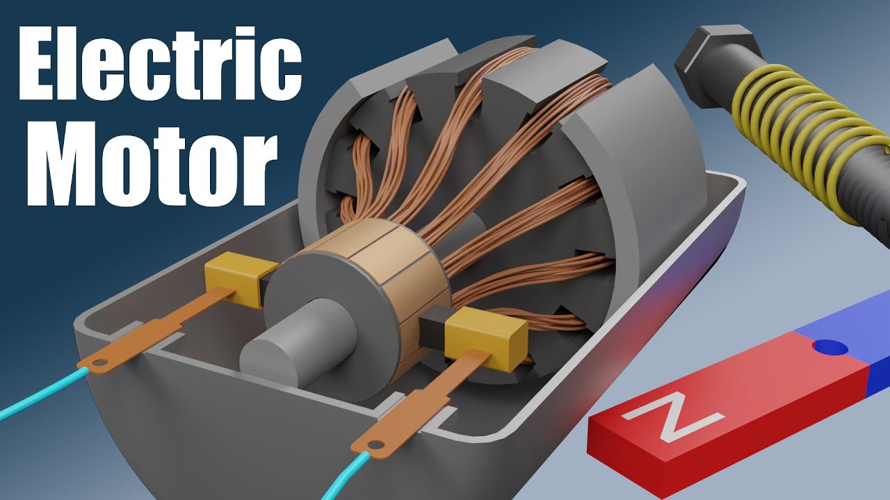
- Stator: This is the stationary part of the motor. Think of it as the motor's "house." It contains the field windings.
- Rotor: The rotating part, directly connected to the output shaft. It interacts with the magnetic field produced by the stator. There are different types of rotors (squirrel-cage, wound rotor) depending on the motor's application.
- Windings (Coils): These are conductors (typically copper wire) wrapped around a core. When electricity flows through them, they create a magnetic field.
- Commutator (DC Motors): A segmented ring that reverses the current in the rotor windings at appropriate times to maintain rotation. Not present in AC induction motors.
- Brushes (DC Motors): Conductive contacts that slide against the commutator, providing the electrical connection to the rotor windings. Again, absent in AC induction motors.
- Bearings: Support the rotor and allow it to spin freely with minimal friction.
- Air Gap: The small space between the rotor and stator. This gap is crucial for the magnetic field to interact and cause rotation. A too-small or inconsistent air gap can lead to friction and motor failure.
Important specs to consider when looking at motors include:
- Voltage (V): The electrical potential difference required for the motor to operate.
- Current (Amps, A): The amount of electrical current the motor draws.
- Power (Watts, W or Horsepower, HP): The rate at which the motor does work. Horsepower is a common unit, especially in automotive applications (1 HP ≈ 746 W).
- Speed (RPM): Revolutions Per Minute – how fast the motor's shaft rotates.
- Torque (Nm or lb-ft): The twisting force the motor can exert. This is crucial for applications requiring high starting power or load-carrying capacity.
- Efficiency (%): The ratio of output power to input power. No motor is 100% efficient; some energy is lost as heat.
Symbols – Understanding the Wiring Diagram
Electric motor diagrams use specific symbols to represent various components and connections. Understanding these symbols is vital for troubleshooting and repair. Here's a quick rundown:
- Straight Lines: Represent wires or electrical conductors. Thicker lines often indicate higher current-carrying capacity.
- Circles: Can represent different things depending on what's inside. A circle with an "M" inside typically signifies the motor itself.
- Zigzag Lines: Usually indicate a resistor or coil.
- Switches: Represented by a break in a line with a lever or arrow showing the switching action.
- Ground: Typically represented by three horizontal lines decreasing in size.
- Dotted Lines: Often indicate a mechanical linkage or connection, rather than an electrical one.
- Color Coding: Wires are often color-coded (e.g., black for ground, red for positive). This helps in tracing circuits and avoiding wiring errors.
Pay close attention to the wiring diagram's legend or key. It will provide specific definitions for any symbols used in that particular diagram.
How It Works – The Principle of Electromagnetism
At its core, an electric motor works based on the principle of electromagnetism. A current-carrying conductor placed in a magnetic field experiences a force. This force is what causes the rotor to turn.
Here's a simplified breakdown of the process:
- Creating a Magnetic Field: When electricity flows through the windings in the stator, it creates a magnetic field. The strength of this field is directly proportional to the current flowing through the windings.
- Interaction of Magnetic Fields: The rotor also contains windings (or in some cases, permanent magnets). The magnetic field produced by the stator interacts with the magnetic field of the rotor.
- Force and Rotation: The interaction of these magnetic fields creates a force that tries to align the fields. Since the rotor is free to rotate, it moves to align itself with the stator's magnetic field.
- Continuous Rotation: To keep the motor spinning, the magnetic field's direction needs to be constantly changed. In a DC motor, this is achieved using a commutator and brushes, which reverse the current in the rotor windings. In an AC induction motor, the alternating current itself causes the magnetic field to rotate.
The type of motor (DC brushed, DC brushless, AC induction, etc.) determines the specific mechanism for achieving continuous rotation, but the fundamental principle of electromagnetic force remains the same.
Real-World Use – Basic Troubleshooting
Understanding the basics allows you to perform some basic troubleshooting:
- Motor Not Starting: Check the power supply first. Is the correct voltage reaching the motor? Use a multimeter to verify. Also, check for blown fuses or tripped circuit breakers.
- Motor Runs Slowly: Could indicate a low voltage supply, worn brushes (in DC motors), or excessive load. Check the motor's rated voltage and compare it to the actual voltage being supplied. Excessive friction in the bearings or a binding mechanical load can also slow it down.
- Motor Overheating: This can be caused by excessive current draw, often due to a short circuit in the windings or an overloaded motor. Immediately disconnect the power and investigate. Overheating can damage the windings and lead to permanent motor failure.
- Noisy Operation: Grinding or squealing noises often indicate worn bearings. Replace the bearings if necessary. Clicking or sparking sounds in a DC motor can indicate worn or damaged brushes or a damaged commutator.
Remember to always disconnect the power before attempting any repairs!
Safety – Highlighting Risky Components
Electric motors can be dangerous if mishandled. Here are some key safety considerations:
- High Voltage: Motors operating at high voltages (especially AC motors) can deliver a lethal shock. Always disconnect the power before working on the motor.
- Rotating Parts: Keep hands and loose clothing away from rotating parts. Use appropriate guards and safety shields.
- Capacitors: Some motors contain capacitors, which can store a dangerous electrical charge even after the power is disconnected. Discharge capacitors properly before handling them.
- Overheating: As mentioned earlier, overheating motors can be a fire hazard. Never operate a motor that is excessively hot to the touch.
Important: If you are not comfortable working with electrical circuits, consult a qualified electrician. Safety should always be your top priority.
Finally, to help you even further, we've compiled a comprehensive electrical motor diagram as discussed throughout the article. This diagram serves as an invaluable resource, providing a visual guide to components, connections, and functionalities. You can download the diagram here.