How Does A Tesla Engine Work
So, you're diving into the world of Tesla motors? Excellent choice! Understanding how these electric marvels work isn't just about bragging rights; it's about gaining a serious edge when it comes to repairs, upgrades, and even just appreciating the engineering that goes into these vehicles. This guide will break down the intricacies of a Tesla motor, giving you the knowledge you need to confidently approach maintenance and modifications. We'll explain the fundamental components and operating principles, all explained in a way that is easy to grasp.
Why Understand the Tesla Motor?
Why should you even bother learning this? Well, consider this: unlike traditional internal combustion engines (ICE), Tesla motors have far fewer moving parts, making them inherently more reliable. However, when something *does* go wrong, understanding the system is crucial for accurate diagnosis and repair. Also, the high-voltage components require extra care when troubleshooting.
- DIY Repairs: Performing basic maintenance tasks and repairs yourself can save you a considerable amount of money.
- Performance Tuning: Understanding the motor's limitations allows for informed performance modifications.
- Troubleshooting: Knowing the inner workings helps you identify and diagnose issues more effectively.
- General Knowledge: Simply appreciating the innovative technology behind Tesla vehicles.
Key Specs and Main Parts
Let's start with the basics. Tesla utilizes primarily induction motors, although some models may use permanent magnet synchronous reluctance motors (PMSynRM), particularly in rear drive units for improved efficiency. These motors are AC (Alternating Current) powered and typically operate at high voltage.
Main Components:
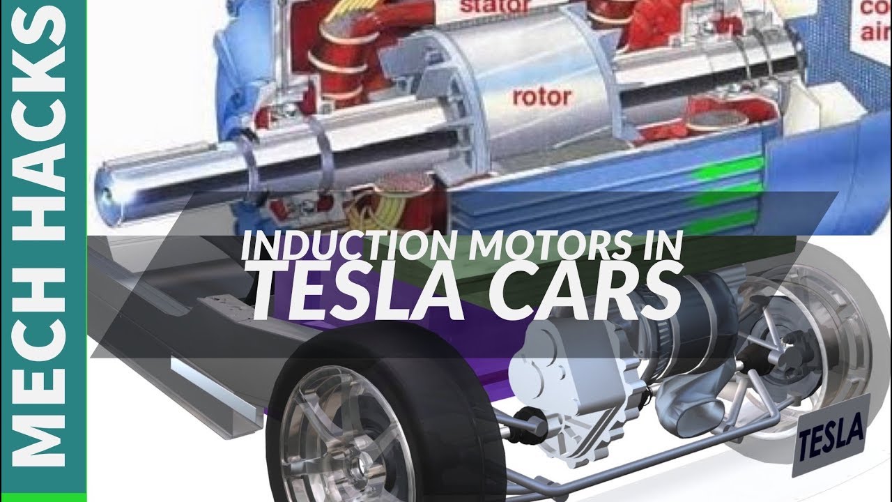
- Stator: The stationary part of the motor, containing windings that create a rotating magnetic field when energized.
- Rotor: The rotating part of the motor, which interacts with the stator's magnetic field to produce torque. In an induction motor, this is a "squirrel cage" design – a series of conductive bars connected by end rings. In a PMSynRM, the rotor contains permanent magnets.
- Inverter: Converts DC (Direct Current) from the battery pack to AC for the motor, and controls the frequency and voltage to regulate motor speed and torque.
- Gearbox (Reduction Gear): Reduces the high RPM of the motor to a more usable speed for the wheels, increasing torque in the process. Typically a single-speed gearbox.
- Cooling System: A liquid cooling system that dissipates heat generated by the motor, inverter, and gearbox. Essential for maintaining optimal performance and preventing damage.
- Resolver/Encoder: A sensor that provides feedback on the rotor's position and speed to the inverter, enabling precise motor control.
- Motor Controller (Part of the Inverter): Regulates the current flow to the motor windings and governs overall performance.
Key Specs (varies by model):
- Voltage: Typically 300-450 VDC (battery pack voltage)
- Power Output: Ranging from 200 kW (approx. 268 hp) to over 500 kW (approx. 670 hp)
- Torque: Extremely high and available almost instantly, contributing to Tesla's rapid acceleration. Ranges from 300 lb-ft to over 700 lb-ft.
- RPM: Can reach over 18,000 RPM, far exceeding that of an internal combustion engine.
Understanding Motor Diagrams
Motor diagrams show the wiring and connection between the components. These are usually complex and very specific to the model, and so, can be difficult to interpret. That said, here is an example of common symbols and connections.
Common Symbols and What They Represent:
- Solid Lines: Indicate electrical wiring or cabling.
- Dashed Lines: Often represent control signals or communication lines (e.g., CAN bus).
- Color Coding: Critical for identifying wire functions. Common colors include:
- Orange: High-voltage DC power
- Blue: Control signals
- Black: Ground
- Red: Low Voltage DC power
- Icons: Represent specific components, such as:
- Rectangles: Often represent electronic modules (e.g., inverter, motor controller).
- Circles/Coils: Represent motor windings.
- Squares with arrows: Represent sensors (e.g., resolver, temperature sensors).
Diagrams also include values that are critical to correctly diagnose faults or specify replacement parts. For example, voltage, current, resistance and capacitance. Using the correct diagram with the correct values is critical.
How It Works: The Tesla Motor in Action
Here's a simplified explanation of the Tesla motor's operation:
- DC Power from Battery: The high-voltage battery pack provides DC power to the inverter.
- Inverter Conversion: The inverter converts the DC power into three-phase AC power. The inverter's switching frequency and voltage amplitude precisely control the motor's speed and torque.
- Rotating Magnetic Field: The three-phase AC power is fed to the stator windings, creating a rotating magnetic field. The frequency of the AC power determines the speed of the rotating magnetic field.
- Rotor Interaction (Induction Motor): In the rotor, the rotating magnetic field induces a current in the conductive bars of the squirrel cage. This induced current creates its own magnetic field, which interacts with the stator's field, generating torque and causing the rotor to spin. The rotor always spins slightly slower than the rotating magnetic field; this difference is called "slip."
Rotor Interaction (PMSynRM): In the PMSynRM motor, the rotor contains permanent magnets, which directly interact with the rotating magnetic field produced by the stator, creating torque and causing the rotor to rotate in sync with the field. - Torque Transfer: The rotor's rotation is transmitted to the gearbox, which reduces the speed and increases the torque delivered to the wheels.
- Feedback Loop: The resolver/encoder provides feedback to the inverter about the rotor's position and speed. This feedback allows the inverter to precisely control the motor, optimizing performance and efficiency.
- Regenerative Braking: When decelerating, the motor acts as a generator, converting kinetic energy back into electrical energy and storing it in the battery pack. This is called regenerative braking, and it improves efficiency.
Real-World Use: Basic Troubleshooting Tips
While deep-diving into motor repair requires specialized tools and knowledge, here are some basic troubleshooting steps you can take:
- Check for Error Codes: Use an OBD-II scanner to check for error codes related to the motor, inverter, or battery system. These codes can provide valuable clues about the problem.
- Inspect Cooling System: Ensure the cooling system is functioning correctly. Check for leaks, proper coolant levels, and radiator fan operation. Overheating can damage the motor and inverter.
- Visual Inspection: Look for any visible signs of damage to the motor, inverter, or wiring. Check for loose connections, corroded terminals, or damaged insulation.
- Battery Health: Low voltage, high internal resistance, and unbalanced cell voltages can create issues with motor operation. Check battery pack health, with the understanding that this operation requires special training and equipment.
- Check Gearbox Oil Level: Low oil level can cause the gearbox to overheat and fail.
Example Scenario: If you experience reduced power or acceleration, and the error code indicates an issue with the resolver, you might start by checking the resolver's wiring and connections. If the wiring is intact, the resolver itself may need to be replaced.
Safety First: High-Voltage Awareness
WARNING: Tesla motors and inverters operate at extremely high voltages. Working with these components can be lethal if proper safety precautions are not followed.
- Always disconnect the high-voltage battery pack before working on the motor or inverter. This requires specialized training and equipment, including high-voltage gloves and a voltage meter capable of reading high DC voltages.
- Verify that the high-voltage system is completely discharged before touching any components.
- Never work alone. Have someone present who can assist in case of an emergency.
- Consult the Tesla service manual for specific safety procedures and warnings.
- If you are not comfortable working with high-voltage systems, seek professional assistance from a qualified technician.
- Never assume it is safe to work on high voltage equipment. Always double and triple check the procedures.
Components that pose particular risk:
- Inverter: Converts DC to AC, generates high voltage.
- Battery Pack: The main source of high-voltage DC power.
- Wiring Harnesses: Contain high-voltage cables.
By understanding the principles and components described above, you can better understand how the Tesla drive system works.
For a more detailed diagram specific to your Tesla model, you can download it here: [LINK TO DIAGRAM - Placeholder - Since I can't host a file, replace this with an actual downloadable file link]. This diagram will provide you with a visual representation of the motor and its components, further enhancing your understanding and troubleshooting capabilities.