How Does A Tesla Motor Work
So, you're keen to understand the guts of a Tesla motor? Excellent! This isn't just about idle curiosity. Grasping the inner workings of your electric vehicle (EV) motor allows for informed maintenance, potential repairs (though proceed with caution!), and a deeper appreciation of the technology powering your ride. We're talking about understanding the principles behind regenerative braking, diagnosing performance issues, and even potentially undertaking modifications – though always be mindful of warranty implications.
Key Specs and Main Parts of a Tesla Motor
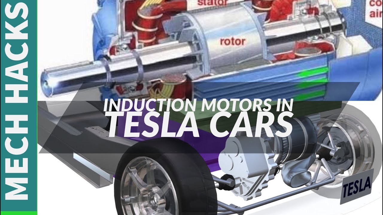
Tesla primarily uses induction motors, also known as AC induction motors. While some models, like the Model 3 Performance, have incorporated permanent magnet synchronous reluctance motors (PMSynRM) for increased efficiency and power density, the induction motor remains a core component in many of their vehicles. Let's break down the key components:
- Stator: The stationary part of the motor. It houses the stator windings – coils of copper wire wrapped around a laminated steel core. These windings are energized with AC electricity, creating a rotating magnetic field. Think of it as the 'engine block' of the electric motor.
- Rotor: The rotating part of the motor. In an induction motor, the rotor is typically a "squirrel cage" design. This consists of conductive bars (usually aluminum or copper) embedded in a laminated steel core and shorted at both ends by end rings. It's called a "squirrel cage" because its shape resembles a rodent's exercise wheel. The rotor's job is to rotate according to the magnetic field.
- Inverter: This vital component converts the DC power from the battery pack into the AC power required by the stator windings. It's essentially the motor's power control center. It handles frequency and amplitude modulation of the AC current.
- Resolver/Encoder: This sensor provides feedback about the rotor's position and speed to the motor controller. It's crucial for precise motor control and regenerative braking. You need to understand it, or the motor will not rotate at the correct speed.
- Cooling System: Electric motors generate heat, especially under heavy load. Tesla motors employ sophisticated cooling systems, typically using liquid coolant circulating through channels within the motor housing and inverter.
- Gearbox (Reduction Gear): Because electric motors produce high torque at low speeds, a single-speed reduction gearbox is used to reduce the motor's high RPM to a usable speed for the wheels.
Understanding Symbols and Lines in a Tesla Motor Diagram
Electrical diagrams use standard symbols to represent components. Here are a few you'll likely encounter:
- Coils/Inductors: Represented by a series of loops. In the diagram, they denote the stator windings.
- Resistors: Shown as a zigzag line. Represents resistance in the circuit.
- Capacitors: Two parallel lines. Stores electrical energy.
- Ground: Usually represented by a series of horizontal lines, often decreasing in length. This is the reference point for the circuit.
- Voltage Source: A circle with a + and - sign. Represents the battery or DC power source.
- Solid Lines: Indicate electrical conductors or wiring.
- Dotted Lines: Often represent mechanical linkages or communication signals.
- Color Coding: Colors in wiring diagrams typically denote the wire's function. For example, red might be positive, black might be ground, and other colors indicate specific signal wires. Consult the specific diagram's key for accurate color coding.
Understanding the "flow" of electricity, represented by arrows, is key. The arrows indicate the direction of current flow, helping you trace the path of electricity through the motor and its control systems.
How a Tesla Motor Works: A Step-by-Step Explanation
Here's a simplified explanation of the Tesla motor's operation:
- DC Power Conversion: The high-voltage battery pack supplies DC power to the inverter.
- AC Power Generation: The inverter converts the DC power into three-phase AC power. The frequency and amplitude of this AC power are controlled by the motor controller, based on driver input (accelerator pedal) and feedback from the resolver/encoder.
- Rotating Magnetic Field: The three-phase AC power is fed into the stator windings. These windings are arranged to create a rotating magnetic field within the stator. The speed of this rotating field is determined by the frequency of the AC power. This speed is called the synchronous speed.
- Rotor Induction: The rotating magnetic field induces a current in the rotor bars. This induced current creates its own magnetic field around the rotor.
- Torque Generation: The interaction between the stator's rotating magnetic field and the rotor's induced magnetic field creates a torque, causing the rotor to rotate. The rotor always rotates slightly slower than the synchronous speed of the stator's magnetic field. This difference in speed is called slip. The amount of slip determines the torque produced by the motor.
- Power Transmission: The rotating rotor's mechanical energy is transferred through the gearbox to the wheels, propelling the vehicle.
- Regenerative Braking: When the driver decelerates, the motor acts as a generator. The kinetic energy of the vehicle is used to spin the rotor, which induces a current in the stator windings. This current is fed back to the inverter, which converts it back into DC power and sends it to the battery pack, recharging it.
Real-World Use: Basic Troubleshooting Tips
While in-depth motor repair is often best left to trained professionals, here are a few basic troubleshooting tips you can use:
- Reduced Performance: If you notice a significant drop in acceleration or range, it could indicate a motor issue. Check for error messages on the car's display.
- Unusual Noises: Grinding, whining, or clicking sounds from the motor area could indicate bearing failure or other mechanical problems.
- Overheating: If the motor overheats frequently, it could indicate a problem with the cooling system. Check coolant levels and look for leaks.
- Error Codes: Use an OBD-II scanner compatible with Tesla vehicles to check for error codes related to the motor or inverter.
Important: Before attempting any troubleshooting, consult your Tesla owner's manual and be aware of warranty limitations. Many components are high-voltage and require specialized knowledge and equipment to handle safely.
Safety Considerations: High-Voltage Hazards
Working on an electric vehicle's motor and inverter involves dealing with extremely high voltages. Even after the vehicle is turned off, capacitors can retain a dangerous charge. Never attempt to disassemble or repair the motor or inverter without proper training and safety equipment, including high-voltage gloves and a voltmeter specifically designed for high-voltage applications.
WARNING: High-voltage electricity can cause severe injury or death. Always disconnect the high-voltage battery pack and verify that all capacitors are discharged before working on any electrical components. If you are not comfortable working with high-voltage electricity, consult a qualified EV technician.
Be particularly careful around the inverter, the high-voltage battery pack, and the wiring connecting these components to the motor. Short circuits can cause fires and explosions.
Understanding the Tesla motor is a journey, not a destination. This overview provides a solid foundation. Remember that this is a complex system, and further research and training are essential for anyone considering advanced repairs or modifications.
To aid in your understanding, we have a detailed motor diagram available for download. It provides a visual representation of the components and their relationships. This diagram will enhance your learning experience and serve as a valuable reference tool.