How Does An Electric Motor Work
Alright, let's dive into the heart of electric motors. Whether you're tinkering with an electric car, a power tool, or even a sophisticated robotics project, understanding how these devices convert electrical energy into rotational motion is crucial. This guide will break down the core principles using a detailed technical explanation and diagram analysis, so you can better understand their operation, troubleshoot issues, and even plan modifications. We've got the detailed diagram available for download later on – stick with me.
Purpose: Why Understanding Electric Motor Diagrams Matters
Why bother learning the intricacies of an electric motor diagram? Several reasons. Firstly, for effective repairs. Knowing the layout of windings, brushes, and other components lets you pinpoint the source of a problem faster than just guessing. Secondly, for informed modifications. If you're considering upgrading a motor, understanding its limitations and how different parts interact is essential. Finally, simply for deeper understanding. It's satisfying to know how things work, and this knowledge empowers you to tackle more complex projects.
Key Specs and Main Parts
Before we delve into the diagram, let’s define some key specifications and main parts that define an electric motor:
- Voltage (V): The electrical potential difference required to power the motor. Motors are rated for specific voltages (e.g., 12V, 24V, 120V).
- Current (A): The flow of electrical charge through the motor. Higher current often equates to higher torque, but also more heat.
- Power (W or HP): The rate at which the motor converts electrical energy into mechanical energy (Watts) or horsepower (HP). Calculated by Power (W) = Voltage (V) x Current (A).
- Speed (RPM): Revolutions Per Minute – how fast the motor shaft rotates.
- Torque (Nm or lb-ft): The rotational force the motor can exert. This determines the motor's ability to overcome resistance and turn a load.
- Efficiency (%): The percentage of electrical power converted into mechanical power. The rest is lost as heat.
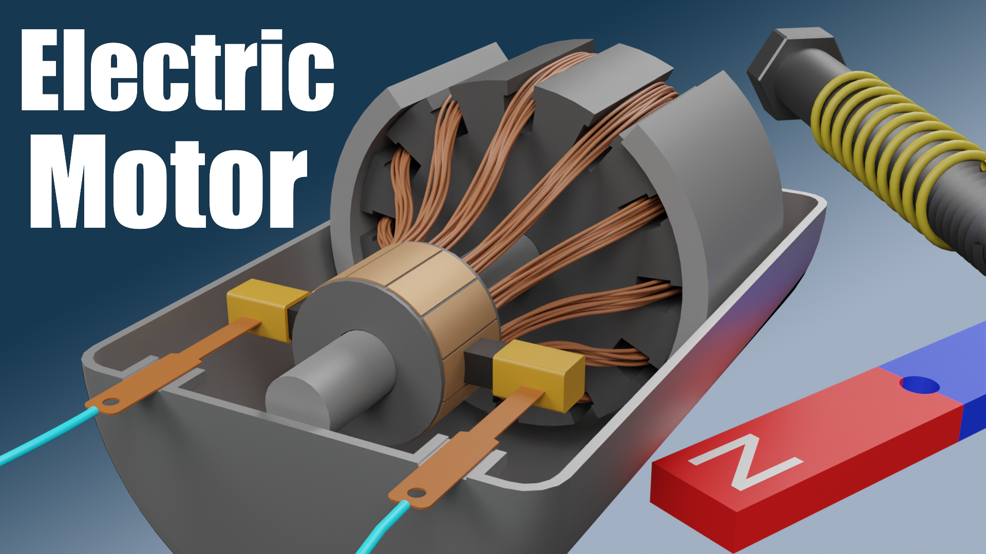
The main parts you'll find represented in the diagram are:
- Stator: The stationary part of the motor. It typically contains the field windings that create a magnetic field.
- Rotor (Armature): The rotating part of the motor. It usually contains windings that interact with the stator's magnetic field, producing torque. In some designs, the rotor can be a permanent magnet.
- Commutator: A segmented ring connected to the rotor windings. It reverses the current flow in the rotor windings at appropriate times to maintain continuous rotation (primarily in DC motors).
- Brushes: Conductive blocks (usually carbon) that make electrical contact with the commutator, allowing current to flow to the rotor windings.
- Field Windings: Coils of wire wrapped around the stator that, when energized, create a magnetic field. These can be permanent magnets in smaller motors.
- Bearings: Support the rotor and allow it to rotate smoothly with minimal friction.
- Housing: The outer casing of the motor, providing protection and structural support.
- Shaft: The rotating output of the motor, used to drive the load.
Symbols: Understanding the Diagram Language
Motor diagrams use standard symbols to represent electrical and mechanical components. Here’s a breakdown of common symbols you'll encounter:
- Straight lines: Represent wires or electrical connections. Thicker lines might indicate heavier gauge wires for higher current capacity.
- Coils (spiral symbol): Represent windings, either in the stator or rotor. The number of turns and the thickness of the wire affect the magnetic field strength.
- Brushes (rectangular blocks touching a segmented circle): Indicate the brushes making contact with the commutator.
- Resistors (zigzag line): Represent electrical resistance, used for controlling current or voltage.
- Capacitors (two parallel lines): Used for smoothing voltage or current, or for power factor correction.
- Ground symbol (stacked horizontal lines): Indicates a connection to earth ground, providing a return path for current and a safety measure.
- Voltage Source (circle with +/- signs): Shows the source of electrical power.
- Arrows: Indicate the direction of current flow or the direction of rotation.
- Color Coding: Typically, red indicates positive voltage, black indicates ground or neutral, and other colors (blue, yellow, green) represent different phases or control signals.
How It Works: The Electromechanical Dance
The core principle of an electric motor is based on the interaction between magnetic fields. Here’s the step-by-step breakdown:
- Magnetic Field Creation: When current flows through the stator windings (the field windings), it generates a magnetic field. The strength of this field is proportional to the current flowing through the windings and the number of turns in the coil. This is the electromagnetic part.
- Rotor Interaction: The rotor also has windings. When current is supplied to these windings (via the brushes and commutator in a DC motor), it also generates a magnetic field. The interaction between the stator's magnetic field and the rotor's magnetic field creates a force.
- Torque Generation: The magnetic fields of the stator and rotor interact, creating a torque – a rotational force. This force tries to align the magnetic poles of the rotor with the magnetic poles of the stator.
- Commutation (in DC motors): As the rotor turns, the commutator reverses the direction of current flow in the rotor windings. This ensures that the magnetic field of the rotor is always oriented in a way that maximizes the torque. Without commutation, the rotor would simply align with the stator field and stop. The commutator is crucial for continuous rotation in DC motors.
- Continuous Rotation: The continuous interaction of the magnetic fields and the reversing current (in DC motors) result in continuous rotation of the rotor, which drives the motor shaft.
Simplified Analogy: Think of it like two bar magnets. If you hold two magnets near each other, they will either attract or repel, depending on their orientation. In an electric motor, the stator is like one magnet (electromagnet), and the rotor is like another magnet (electromagnet). The motor's design continuously adjusts the "magnets" to keep them repelling, thus forcing rotation.
Real-World Use: Basic Troubleshooting Tips
Here are some basic troubleshooting tips based on your understanding of the motor diagram:
- Motor Not Running: Check the voltage supply and connections first. Use a multimeter to verify voltage at the motor terminals. Then, inspect the brushes (if it's a DC motor) for wear and tear. A worn brush won't make proper contact with the commutator. Check the wiring for breaks or shorts, especially in the windings.
- Motor Running Slowly or Weakly: Could be due to low voltage, worn brushes, or a partially shorted winding. Check the armature resistance; a significantly lower-than-expected resistance indicates a short. Look for signs of overheating, which can damage the windings' insulation.
- Motor Overheating: Often caused by excessive load, poor ventilation, or a shorted winding. Reduce the load or improve ventilation. A shorted winding will draw excessive current and cause overheating.
- Sparking at the Brushes: Can be normal to a degree, but excessive sparking indicates worn brushes, a dirty or damaged commutator, or an overloaded motor.
Safety: Handle with Care
Electric motors, especially larger ones, can be dangerous if mishandled. Always disconnect the power source before working on a motor. Capacitors can store a dangerous charge even after the power is disconnected – discharge them safely using a resistor. Be especially careful when working with high-voltage motors. The windings themselves can become hot during operation, so avoid touching them immediately after use. Ensure adequate ventilation to prevent overheating.
Remember to exercise caution and double-check your work before applying power. A mistake can lead to electrical shock, fire, or damage to the motor.
Now that you have a grasp of how electric motors work, you’re better equipped to diagnose, repair, and even modify them. And as promised, you can download the detailed diagram we discussed to get a visual reference. This will help you trace connections, identify components, and deepen your understanding even further.