How To Auto Start Nissan Rogue
Welcome, fellow gearheads, to an in-depth exploration of the Nissan Rogue's auto start system. This isn't just about convenience; understanding the system's architecture can be invaluable for troubleshooting, diagnostics, modifications, or even just satisfying your curiosity. Whether you're wrestling with a malfunctioning remote start or planning to integrate a custom aftermarket solution, this breakdown will arm you with the knowledge you need. We'll dissect the system diagram, covering everything from wiring schematics to component functions, so you can confidently tackle any Rogue auto start challenge.
Why This Diagram Matters
The auto start system in your Nissan Rogue is a complex web of sensors, actuators, and control modules all working in concert. Having a comprehensive wiring diagram is essential for several reasons:
- Troubleshooting: When the auto start fails, the diagram helps you trace the signal path, pinpointing the faulty component – a faulty relay, a broken wire, or a malfunctioning sensor.
- Repairs: If a wire needs splicing or a component needs replacing, the diagram ensures you make the correct connections, preventing further damage.
- Modifications: Planning to add an aftermarket remote start or alarm system? The diagram shows you where to tap into the existing system safely and effectively.
- Understanding: Simply understanding how the system works can empower you to diagnose minor issues yourself, saving time and money at the mechanic.
Key Specs and Main Parts
Before diving into the diagram, let's familiarize ourselves with the core components of the Nissan Rogue's auto start system. Keep in mind that exact components and their configurations can vary slightly depending on the model year and trim level.
- Remote Key Fob: The user interface for initiating the auto start sequence. It transmits a radio frequency (RF) signal to the vehicle.
- BCM (Body Control Module): The brains of the operation. The BCM receives the RF signal from the key fob, verifies the vehicle's safety parameters, and then initiates the start sequence. It often integrates with the immobilizer system.
- Immobilizer System: A crucial security feature that prevents unauthorized starting. It typically involves a transponder chip in the key and a receiver in the ignition switch, communicating with the ECM (Engine Control Module).
- ECM (Engine Control Module): The engine's computer, responsible for controlling fuel injection, ignition timing, and other vital engine functions. The BCM sends a command to the ECM to start the engine.
- Starter Relay: An electrical switch that allows the low-current BCM signal to control the high-current flow to the starter motor.
- Hood Switch: A safety switch that prevents the auto start from engaging if the hood is open.
- Brake Switch: Another safety feature. Auto start will be disabled if the brake pedal is depressed.
- Door Switches: These switches, in some models, can cancel the auto start if a door is opened while the engine is running remotely.
Symbols: Deciphering the Diagram
Wiring diagrams use a standardized set of symbols to represent components and connections. Understanding these symbols is paramount to interpreting the diagram correctly. Here's a breakdown of common symbols you'll encounter:
- Lines: Represent wires. Solid lines indicate direct connections, while dashed lines may indicate shielded wires or connections on separate sheets of the diagram. Line thickness can sometimes indicate wire gauge (thicker lines = thicker wires).
- Colors: Each wire is typically labeled with a color code (e.g., "BLU" for blue, "RED" for red, "BLK" for black). This helps you identify the correct wire during troubleshooting and repair.
- Ground Symbols: Usually depicted as a series of horizontal lines decreasing in size, or a triangle pointing downwards. They indicate the point where the circuit is connected to the vehicle's chassis for grounding.
- Component Symbols: These vary depending on the component. Relays are often represented by a square with a coil symbol inside, switches by a line with a break that opens or closes, and sensors by their specific symbol (e.g., a thermistor symbol for a temperature sensor).
- Connectors: Shown as circles or squares where wires come together. Connector numbers and pin numbers are often indicated to identify specific connections.
- Fuses: Represented by a wavy line inside a rectangle. Fuse amperage ratings are usually indicated next to the symbol.
Pay close attention to wire color codes and connector pin numbers. These are crucial for accurate identification and troubleshooting.
How It Works: The Auto Start Sequence
The auto start process unfolds as follows:
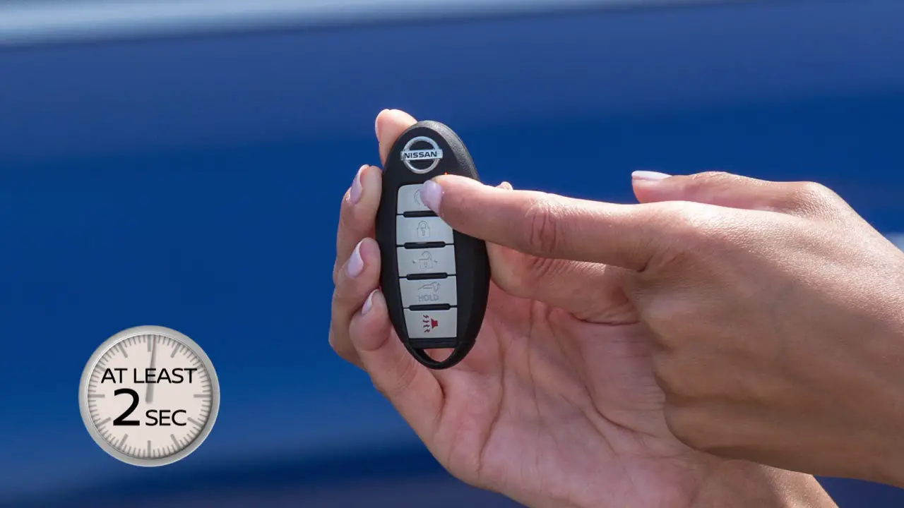
- Remote Activation: You press the auto start button on the key fob. The fob transmits an RF signal containing an encrypted code.
- BCM Reception & Verification: The BCM receives the RF signal and verifies its authenticity against its programmed codes.
- Safety Parameter Checks: The BCM checks various safety parameters, such as hood closed, brake pedal not depressed, gear selector in Park or Neutral, and security system disarmed.
- Immobilizer Bypass (if required): The BCM communicates with the immobilizer system to temporarily bypass it for the duration of the remote start.
- ECM Activation: The BCM sends a signal to the ECM, requesting it to start the engine.
- Starter Motor Engagement: The ECM activates the starter relay, which in turn sends high-current power to the starter motor to crank the engine.
- Engine Start & Monitoring: Once the engine starts, the ECM monitors its operation and makes adjustments as needed. The BCM continues to monitor safety parameters.
- Auto Start Timeout: The engine will run for a pre-determined time (usually 10-15 minutes) and then automatically shut off if no further action is taken.
Real-World Use: Basic Troubleshooting
When the auto start system malfunctions, a systematic approach to troubleshooting is essential. Here are some basic tips:
- Check the Basics: Ensure the key fob battery is good. Try a known good key fob if available.
- Verify Safety Switches: Confirm the hood is fully closed and the brake pedal is not accidentally depressed. Check the functionality of the hood and brake switches with a multimeter.
- Scan for DTCs: Use an OBD-II scanner to check for Diagnostic Trouble Codes (DTCs) related to the auto start system. These codes can provide valuable clues about the problem.
- Check Fuses & Relays: Inspect the fuses and relays associated with the auto start system for any signs of damage or corrosion. Refer to the wiring diagram to locate the correct fuses and relays.
- Wiring Issues: Inspect the wiring harness for any signs of damage, such as cuts, abrasions, or loose connections. Use the wiring diagram to trace the wires and check for continuity.
Example Scenario: The auto start doesn't work, and the hazard lights flash when you press the remote start button. This often indicates a security system issue or a problem with the hood switch. Check the hood switch and any aftermarket security system installations.
Safety: Handling Risky Components
Working with automotive electrical systems can be dangerous. Always disconnect the negative battery terminal before working on any electrical components. Be especially cautious when working with the following:
- Airbag System: Do not tamper with the airbag system. Accidental deployment can cause serious injury. If you need to work near airbag components, consult a qualified technician.
- High-Voltage Wiring: Some newer Rogue models might have mild hybrid systems. Be aware of high-voltage wiring (usually orange cables) and avoid contact.
- Fuel System: When working near the fuel system, take precautions to prevent fires. Disconnect the fuel pump relay and work in a well-ventilated area.
Always consult the vehicle's service manual and follow proper safety procedures. If you're not comfortable working with electrical systems, seek the assistance of a qualified mechanic.
By now, you should have a much better understanding of your Nissan Rogue's auto start system. We have the comprehensive wiring diagram file available for download. With this resource and the knowledge gained here, you'll be well-equipped to tackle any auto start related task.