How To Build An Electric Engine
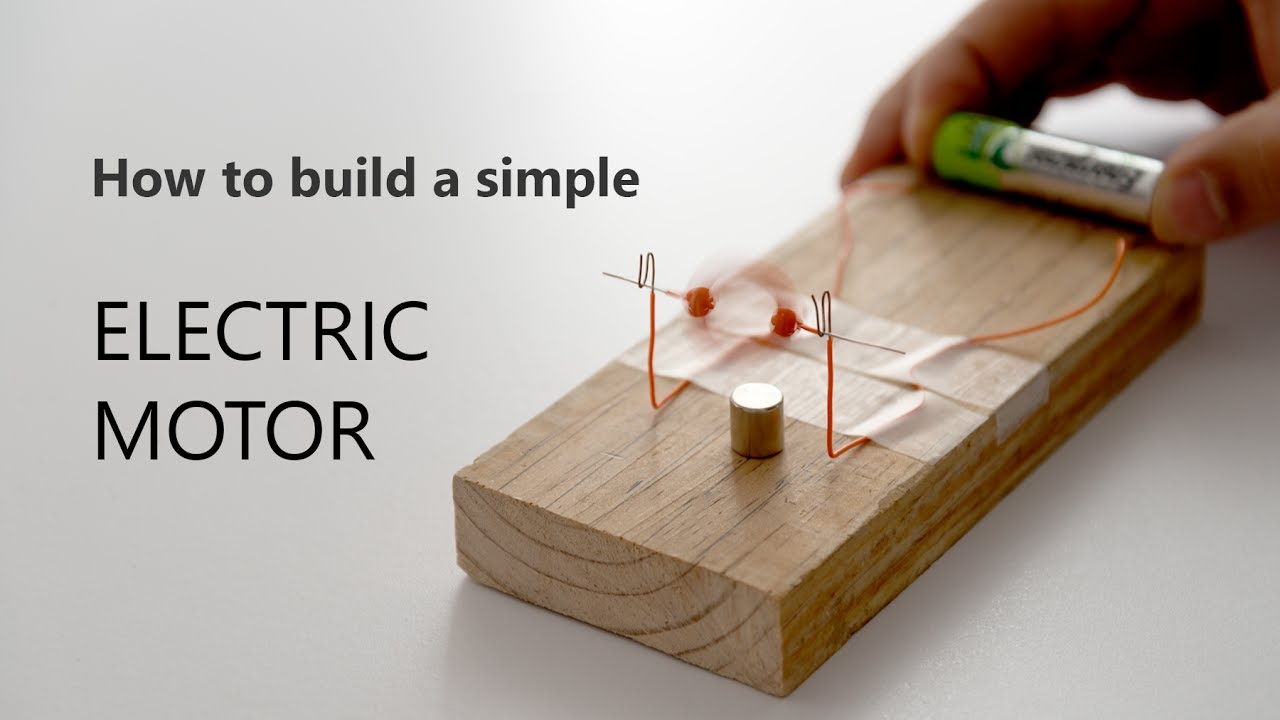
Alright, let's talk about building an electric motor. Now, before you start picturing a complex automotive engine swap, understand that we're focusing on the fundamental principles and a simplified design. This isn't about dropping a Tesla motor into your classic Mustang (though that's cool too!), but rather understanding the core workings and potentially building a small, functional electric motor for a hobby project or learning experience.
Why This Matters: Understanding the Electric Heart
Why bother learning this? There are several reasons. First, it empowers you to understand the inner workings of electric vehicles and other electric-powered devices. If you’re serious about modifying or maintaining your hybrid or EV, knowing the fundamentals is invaluable. Second, understanding electric motor principles helps with troubleshooting. If a motor isn't working, knowing the components and their functions makes diagnosing the problem much easier. Third, it's just plain cool! Building something that converts electrical energy into mechanical energy is a rewarding DIY project, especially if you're a hands-on person who enjoys tinkering.
Key Specs and Main Parts: The Anatomy of an Electric Motor
Let's dive into the main components and some key specifications to consider when designing or building your motor. We'll be focusing on a simple brushed DC motor design for this explanation.
Core Components:
- Stator: The stationary part of the motor. In a simple brushed DC motor, this is usually a permanent magnet or an electromagnet formed by coils of wire. The stator provides the static magnetic field.
- Rotor (Armature): The rotating part of the motor. It consists of coils of wire wrapped around an iron core. When current flows through these coils, they create a magnetic field that interacts with the stator's magnetic field, causing rotation.
- Commutator: A segmented ring that reverses the direction of current flow in the rotor coils at specific intervals. This is crucial for maintaining continuous rotation. Think of it as the motor's "brain" for switching polarity.
- Brushes: Conductive contacts (usually made of carbon) that press against the commutator, providing the electrical connection between the power source and the rotor coils.
- Shaft: The rotating rod connected to the rotor, which transfers the motor's mechanical energy to the load (e.g., turning a wheel).
- Housing: The outer casing that protects the motor's internal components.
Key Specifications:
- Voltage (V): The electrical potential difference required to operate the motor.
- Current (A): The amount of electrical current the motor draws during operation. Higher current usually means more torque.
- Speed (RPM - Revolutions Per Minute): The rotational speed of the motor's shaft.
- Torque (Nm or lb-ft): The twisting force the motor can produce. This is critical for determining the motor's ability to handle loads.
- Power (W or HP): The rate at which the motor can do work. Calculated as Power = Torque x Speed.
- Efficiency (%): The ratio of mechanical power output to electrical power input. No motor is 100% efficient; some energy is lost as heat.
Understanding the Diagram: Symbols and Conventions
A circuit diagram for a simple DC motor is relatively straightforward. Here's a breakdown of common symbols:
- Straight Line: Represents a wire or conductor.
- Resistor Symbol (Zigzag Line): Represents resistance in the circuit, which can be inherent in the motor's windings.
- Battery Symbol (Long and Short Parallel Lines): Represents the DC power source. The longer line indicates the positive terminal.
- Motor Symbol (Circle with an "M" inside): Represents the electric motor itself.
- Switch Symbol (Line with a Break): Represents a switch that can open or close the circuit.
Colors are often used to indicate voltage levels or signal types. Red is typically used for positive voltage, black for ground (0V), and other colors for various signals or control lines.
How It Works: The Magic of Electromagnetism
The principle behind an electric motor is electromagnetism. When an electric current flows through a wire, it creates a magnetic field around the wire. The strength of the magnetic field is proportional to the current. When a wire carrying current is placed within an existing magnetic field (provided by the stator magnets), it experiences a force. The direction of this force is perpendicular to both the direction of the current and the direction of the magnetic field (as described by Fleming's left-hand rule).
In a DC motor, the rotor coils are strategically positioned within the stator's magnetic field. When current flows through the rotor coils, a magnetic force is created, causing the rotor to rotate. As the rotor rotates, the commutator switches the direction of current flow in the coils. This switching action ensures that the magnetic force continues to push the rotor in the same direction, maintaining continuous rotation. The brushes act as the interface, providing a continuous electrical connection to the rotating commutator.
In essence, the electrical energy is converted into mechanical energy through the interaction of magnetic fields and the clever switching action of the commutator and brushes.
Real-World Use: Basic Troubleshooting
Let's consider some basic troubleshooting scenarios:
- Motor Doesn't Spin:
- Check Power Supply: Is the voltage correct? Is the battery charged?
- Check Connections: Are all wires properly connected? Are there any loose connections?
- Check Brushes: Are the brushes worn down or making poor contact with the commutator? Replace them if necessary.
- Check Commutator: Is the commutator dirty or damaged? Clean it carefully with a commutator cleaner or very fine sandpaper.
- Check for Blockage: Is the rotor physically blocked from rotating?
- Motor Spins Slowly:
- Low Voltage: Is the voltage lower than specified?
- High Load: Is the motor overloaded? Reduce the load.
- Worn Brushes: Replace the brushes.
- Binding: Check for mechanical binding or friction.
- Motor Overheats:
- Overload: The motor is working too hard. Reduce the load.
- Insufficient Ventilation: Ensure proper airflow around the motor.
- Short Circuit: There might be a short circuit in the windings. This usually requires professional repair or replacement.
Remember, when troubleshooting, always disconnect the power supply before inspecting the motor.
Safety: Respect the Electrical Potential
Electricity can be dangerous. Here are some key safety precautions:
- High Voltage Capacitors: Electric motors, particularly those used in EVs, often have large capacitors that store a significant electrical charge even after the power is disconnected. These capacitors can deliver a potentially lethal shock. Always discharge capacitors before working on the motor. This often requires specialized tools and knowledge. If you're not comfortable working with high-voltage circuits, seek professional help.
- Short Circuits: Avoid creating short circuits, which can cause fires or damage components.
- Grounding: Ensure proper grounding to prevent electrical shocks.
- Insulation: Always use insulated tools and wear appropriate protective gear, such as gloves and safety glasses.
Working with electricity requires respect and caution. If you're unsure about any aspect of the process, consult a qualified electrician or engineer.
We have a detailed diagram of a simple brushed DC motor, including wiring schematics and parts list. Contact us and we would be happy to share. Now go forth and electrify!