How To Check If Bad Alternator
So, your car's acting up, and you suspect the alternator might be the culprit? You're not alone. The alternator is a critical component of your car's charging system, and a failing one can leave you stranded. This guide will walk you through the process of checking your alternator, providing you with the knowledge and tools to diagnose the issue like a seasoned mechanic. We'll cover the key components, testing procedures, and safety precautions. Let's dive in!
Purpose and Importance of Alternator Diagnostics
Understanding how to diagnose a bad alternator is crucial for several reasons:
- Repair Savings: Identifying a faulty alternator early can prevent further damage to your electrical system and save you money on costly repairs at the shop.
- Preventative Maintenance: Regularly checking your alternator's performance can help you anticipate failures and replace it before it leaves you stranded.
- Electrical System Knowledge: This process provides a deeper understanding of your car's electrical system, empowering you to tackle other DIY repairs.
- Performance Tuning/Modifications: If you're modifying your car with aftermarket accessories (lights, sound systems), understanding your alternator's capacity is vital to avoid overloading the system.
Having a good understanding of the alternator and its functionality is a valuable skill for any DIY mechanic or car enthusiast.
Key Specs and Main Parts of an Alternator
Before we start testing, let's review the key specs and components of a typical automotive alternator:
Main Components:
- Stator: The stationary part containing windings that generate AC voltage when the rotor spins. Think of it as the electricity-generating core.
- Rotor (Armature): A rotating electromagnet that creates a magnetic field when supplied with current. This magnetic field induces voltage in the stator windings.
- Rectifier (Diode Bridge): A set of diodes that convert the AC voltage from the stator into DC voltage, which is what your car's electrical system uses. A failed diode is a common cause of alternator failure.
- Voltage Regulator: Maintains a constant output voltage (typically around 13.5-14.5 volts) to prevent overcharging and damage to the battery and other components. This is a very common cause of issues.
- Brushes: Conduct electricity to the rotor's slip rings, energizing the electromagnet. These wear down over time.
- Slip Rings: Metal rings on the rotor that make contact with the brushes.
- Pulley: Connected to the engine's crankshaft via a belt, driving the rotor.
Key Specifications:
- Voltage Output: Typically 13.5-14.5 volts. This is the most important spec to monitor.
- Amperage Output: The maximum current the alternator can supply (e.g., 90 amps, 120 amps, etc.). Choose higher amperage if you're adding a lot of electrical equipment to the vehicle.
- Operating Speed: The RPM range at which the alternator is designed to operate efficiently.
Understanding Alternator Circuit Symbols
While we won't be using a full-blown electrical schematic in this guide, it's helpful to understand the basic symbols you might encounter when referencing diagrams related to your charging system:
- Lines: Solid lines represent wires connecting different components. The thickness of the line sometimes (but not always) indicates the wire gauge.
- Battery Symbol: Typically represented by a series of alternating long and short lines. Often labeled "+" and "-".
- Ground Symbol: Usually depicted as a series of descending horizontal lines, indicating a connection to the vehicle's chassis (ground).
- Alternator Symbol: Varies, but often shown as a circle with a squiggly line inside (representing the stator windings) and a "D+" or "ALT" label.
- Fuse Symbol: Looks like a squiggly line enclosed in a rectangle or a small loop.
- Diode Symbol: A triangle pointing towards a vertical line. The direction of the triangle indicates the direction of current flow.
Colors are often used to differentiate wires in diagrams. Red typically indicates positive voltage, while black often represents ground. However, wire colors can vary between manufacturers, so always double-check the legend of the diagram you are using.
How the Alternator Works: A Simplified Explanation
The alternator's job is to keep your battery charged and provide power to your car's electrical system while the engine is running.
- The engine's crankshaft turns the alternator's pulley via a belt.
- The pulley spins the rotor inside the alternator.
- The voltage regulator controls the amount of current flowing to the rotor, which creates a magnetic field.
- The rotating magnetic field induces an alternating current (AC) in the stator windings.
- The rectifier (diode bridge) converts the AC voltage from the stator into direct current (DC).
- The voltage regulator maintains a stable DC voltage output (around 13.5-14.5 volts), supplying power to the car's electrical system and charging the battery.
If any of these steps fail, the alternator will not properly charge the battery, leading to a dead battery and potential electrical issues.
Real-World Use: Basic Alternator Troubleshooting
Here are some common symptoms of a failing alternator and how to troubleshoot them:
- Dimming Headlights/Interior Lights: This is a classic sign of a weak alternator struggling to supply enough power. Test with a multimeter, see below.
- Battery Warning Light: Indicates a problem in the charging system. Could be the alternator, battery, or wiring.
- Dead Battery: If your battery keeps dying even after jump-starting, the alternator may not be charging it properly.
- Strange Noises: Whining, grinding, or rattling noises from the alternator area could indicate worn bearings or a failing pulley.
- Electrical Problems: Intermittent issues with power windows, radio, or other electrical accessories can be caused by fluctuating voltage from a bad alternator.
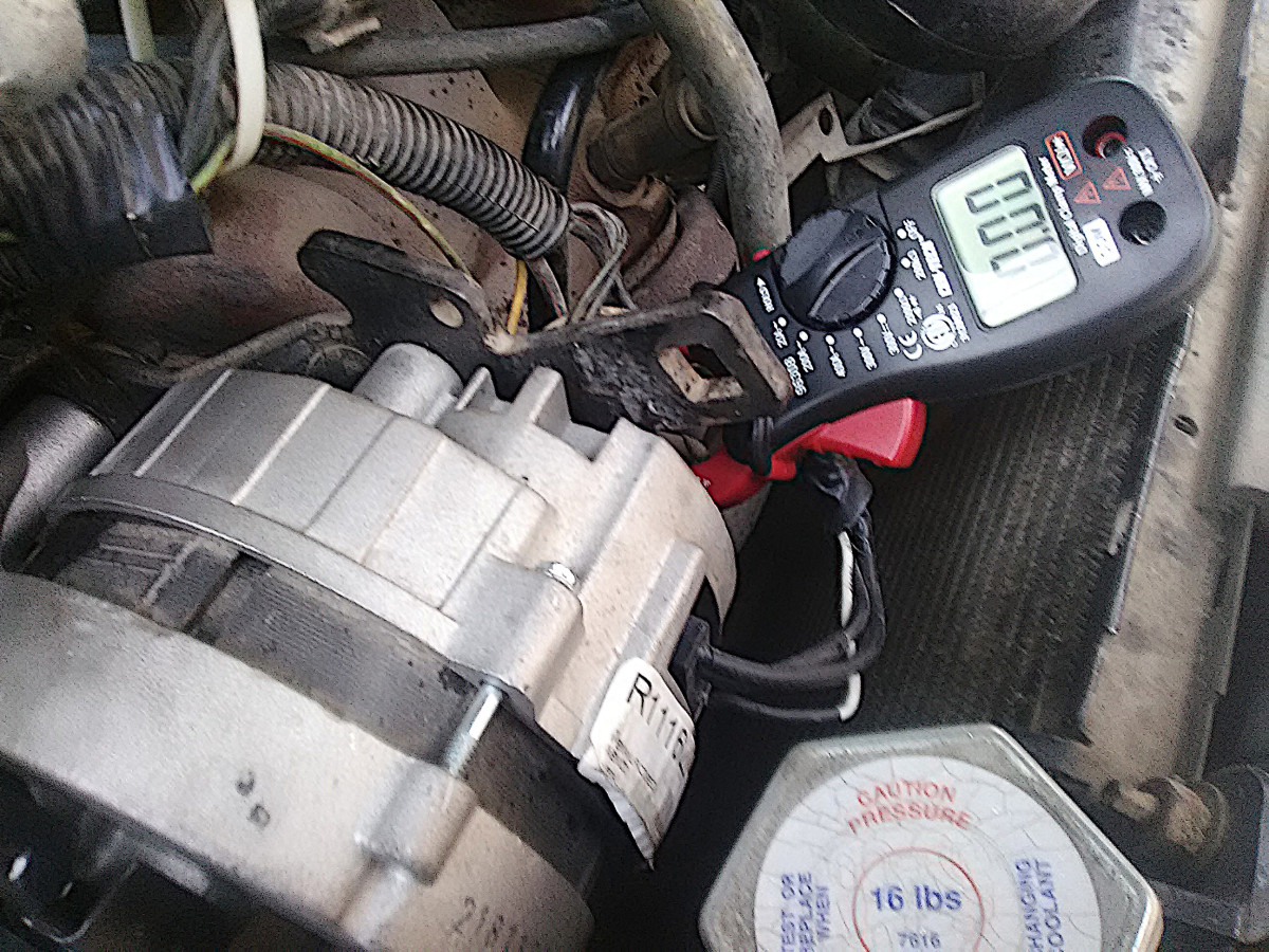
Testing Procedure (with a Multimeter):
- Safety First: Wear safety glasses and disconnect the negative battery cable before working on the electrical system.
- Voltage Test (Engine Off): Connect a multimeter to the battery terminals (red lead to positive, black lead to negative). A fully charged battery should read around 12.6 volts.
- Voltage Test (Engine Running): Start the engine and let it idle. With the multimeter still connected to the battery, the voltage should now read between 13.5 and 14.5 volts. A reading outside this range suggests an alternator problem.
- Load Test (Engine Running): Turn on several electrical accessories (headlights, AC, radio). The voltage should remain within the 13.5-14.5 volt range. If the voltage drops significantly, the alternator may be unable to handle the load.
- Diode Ripple Test (AC Voltage): Set your multimeter to measure AC voltage. With the engine running, connect the multimeter to the battery terminals. A healthy alternator should show very little AC voltage (typically less than 0.5 volts). Higher AC voltage indicates a faulty diode in the rectifier. This requires a good multimeter that can read AC voltage in very small ranges.
Important: A failing battery can sometimes mimic alternator problems. It's a good idea to have your battery load-tested at an auto parts store before assuming the alternator is the issue.
Safety Precautions
Working on your car's electrical system can be dangerous. Here are some essential safety precautions:
- Disconnect the Negative Battery Cable: This is the most crucial step. Disconnecting the negative terminal prevents accidental shorts and potential electrical shocks.
- Wear Safety Glasses: Protect your eyes from sparks and debris.
- Avoid Touching Exposed Wires: Especially when the engine is running.
- Work in a Well-Ventilated Area: Batteries can release hydrogen gas, which is flammable.
- Do Not Wear Jewelry: Metal jewelry can conduct electricity and cause burns.
- Identify Risky Components: The alternator's B+ terminal (the main output terminal) carries high voltage and current. Avoid touching it while the engine is running.
Disclaimer: This guide provides general information and should not be considered a substitute for professional advice. If you are not comfortable working on your car's electrical system, consult a qualified mechanic.
Diagnosing and repairing electrical system components requires skill and precision. The information outlined here is for educational purposes and designed for an experienced DIYer.
We have a detailed alternator system diagram available for download. It provides a visual aid to help you understand the components and wiring of your car's charging system. Contact us if you would like the file to be emailed to you.