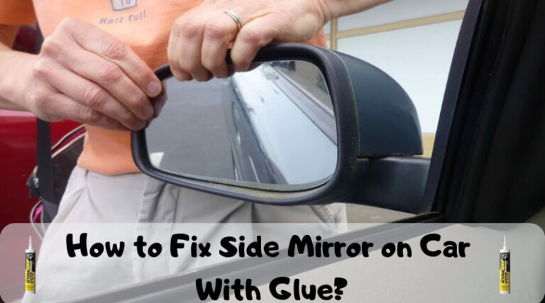
How To Fix Car Side Mirror
So, your side mirror's taken a beating, huh? Whether it's a crack from a stray rock, a complete knock-off thanks to a tight parking spot, or a faulty power adjuster, replacing or repairing a side mirror is a job many experienced DIYers can tackle. Having a good wiring diagram and understanding the components makes the process much smoother. This guide will walk you through understanding a typical car side mirror system, from its basic components to some common troubleshooting tips, allowing you to confidently approach the repair.
Purpose: Why Understanding the Side Mirror Diagram Matters
A car side mirror diagram is more than just a visual aid; it's a crucial tool for several reasons:
- Repairs and Replacements: Identifying the correct wiring for power mirrors, heating elements (defoggers), and integrated turn signals ensures a successful replacement or repair. Incorrect wiring can lead to short circuits, blown fuses, or even damage to the car's electrical system.
- Troubleshooting: When your mirror stops adjusting, the heating element fails, or the turn signal malfunctions, the diagram helps you pinpoint the source of the problem. Is it a faulty switch, a broken wire, or a defective motor? The diagram allows you to systematically trace the circuit and isolate the fault.
- Upgrades and Modifications: Planning to install aftermarket mirrors with additional features like blind-spot monitoring? The diagram is essential for understanding the existing wiring and integrating the new components correctly.
- General Understanding: Even if you're not planning any immediate repairs, studying the diagram gives you a better understanding of your car's electrical system and how its components interact.
Key Specs and Main Parts
A typical car side mirror assembly consists of several key components, each with its specific function:
- Mirror Glass: The reflective surface that provides the driver with a view of the surrounding area. These can be standard, convex (to widen the field of view), or electrochromatic (auto-dimming).
- Mirror Housing: The protective shell that encloses the mirror glass and internal components. It's usually made of plastic or metal.
- Adjustment Motors: These small electric motors control the horizontal and vertical movement of the mirror glass. Most modern mirrors have at least two motors, one for each axis.
- Heating Element (Defogger): A thin resistive heating element bonded to the back of the mirror glass. When activated, it heats the glass to melt ice and clear fog.
- Turn Signal Indicator (Optional): Some mirrors incorporate LED turn signal indicators for increased visibility.
- Blind Spot Monitoring System (BSM) (Optional): More advanced systems may include sensors and indicators for blind-spot monitoring.
- Wiring Harness and Connector: A bundle of wires and a connector that provides the electrical connection between the mirror assembly and the car's electrical system.
- Pivot and Mounting Bracket: This is the mechanism that allows the mirror to fold inwards, usually for parking or to prevent damage from impacts. It also attaches the mirror assembly to the car door.
Key specifications to look for when replacing parts include the mirror's dimensions, the type of glass (standard, convex, electrochromatic), the number of wires in the harness (indicating the features supported), and the mounting style. Make sure the replacement part is compatible with your car's make, model, and year.
Symbols: Decoding the Wiring Diagram
Understanding the symbols used in the wiring diagram is crucial for accurate troubleshooting and repair. Here are some common symbols you'll encounter:
- Solid Lines: Represent wires. Thicker lines often indicate wires that carry more current (e.g., power wires).
- Dashed Lines: May represent grounding connections or shielded wires. Sometimes, they indicate wires bundled together for organization.
- Colors: Wires are typically color-coded (e.g., red for power, black for ground). The diagram will usually include a color key to identify each wire.
- Circles: Often represent connectors or junctions where wires are joined together.
- Rectangles: May represent components like switches, relays, or control modules.
- Motor Symbols: A circle with an "M" inside indicates an electric motor, such as those used for mirror adjustment.
- Resistor Symbols: A zig-zag line represents a resistor, such as the heating element in a defogger mirror.
- Ground Symbol: A series of descending horizontal lines, or a triangle pointing downwards, indicates a ground connection.
- Fuse Symbol: A wavy line within a rectangle, representing a fuse protecting the circuit.
Understanding Wire Colors: Car manufacturers use a standardized color coding system for wires. While not universal, some common conventions are: Red for power (often battery positive), Black for ground, Yellow or Orange for accessory power (switched on with the ignition), and various other colors for signals and control circuits. Always refer to the specific wiring diagram for your car model to confirm the meaning of each color.
How It Works: The Side Mirror System in Action
The basic operation of a side mirror system is relatively straightforward:
- Power Mirrors: When you adjust the mirror using the control switch inside the car, the switch sends signals to the adjustment motors within the mirror assembly. Each motor controls the movement of the mirror glass in one direction (horizontal or vertical). The wiring diagram shows which wires control each motor and how the switch is connected.
- Heated Mirrors: When you activate the heated mirror function (usually through a switch on the dashboard), power is supplied to the heating element on the back of the mirror glass. The heating element heats up, melting ice and clearing fog. The diagram shows the circuit for the heating element, including the fuse, switch, and wiring. A thermostat might be present to regulate the temperature.
- Turn Signal Indicators: When you activate the turn signal, the car's turn signal circuit sends a signal to the LED turn signal indicators in the mirror. The diagram shows how the turn signal circuit is connected to the mirror's LEDs, including any resistors or control circuitry.
Modern side mirrors often incorporate more complex features, such as automatic dimming (electrochromatic mirrors) and blind spot monitoring systems. These features require more sophisticated wiring and control circuitry, which will be reflected in the wiring diagram.
Real-World Use: Basic Troubleshooting Tips
Here are some common side mirror problems and troubleshooting tips:
- Mirror Doesn't Adjust:
- Check the fuse for the power mirror circuit. A blown fuse is a common cause.
- Inspect the wiring harness and connector for damage or corrosion.
- Test the adjustment switch. Use a multimeter to check for continuity when the switch is activated.
- Test the adjustment motors. You can apply direct voltage (usually 12V) to the motor terminals to see if they operate. Be careful not to exceed the rated voltage.
- Heated Mirror Doesn't Work:
- Check the fuse for the heated mirror circuit.
- Inspect the wiring and connector for damage.
- Test the heating element for continuity using a multimeter. An open circuit indicates a faulty heating element.
- Check the switch that activates the heated mirror.
- Turn Signal Doesn't Work:
- Check the bulb or LEDs in the turn signal indicator.
- Inspect the wiring and connector.
- Check the turn signal flasher relay.
Using a Multimeter: A multimeter is your best friend when troubleshooting electrical problems. Learn how to use it to test for voltage, continuity, and resistance. Always disconnect the battery's negative terminal before working on any electrical components to prevent short circuits.
Safety: Handle with Care
Working with car electrical systems can be dangerous if you're not careful. Here are some safety precautions to keep in mind:
- Disconnect the Battery: Always disconnect the negative terminal of the car battery before working on any electrical components. This will prevent accidental short circuits and electric shocks.
- Identify High-Risk Components: The airbag system often has sensors and wiring routed through the door and side mirror area. Be extremely careful when working around these components. Disconnecting the airbag system requires specialized knowledge and should be handled by a qualified technician.
- Use Proper Tools: Use insulated tools designed for automotive electrical work.
- Protect Yourself: Wear safety glasses to protect your eyes from debris and sparks.
- Work in a Well-Ventilated Area: If you're using any solvents or chemicals, work in a well-ventilated area.
- Double-Check Your Work: Before reconnecting the battery, double-check all your wiring connections to ensure they are correct and secure.
Airbag System Warning: Tampering with the airbag system can be extremely dangerous and may result in serious injury or death. If you are not comfortable working around airbags, consult a qualified technician.
Replacing a side mirror is a manageable task with a good understanding of the system and proper tools. Remember to prioritize safety, double-check your work, and don't hesitate to consult a professional if you're unsure about any aspect of the repair.
Remember, we have a general side mirror wiring diagram available for download. It's a valuable resource to supplement the information presented here and can help you visualize the components and wiring connections. Happy wrenching!