How To Fix My Car Air Conditioner
So, your car's AC is blowing hot air again? We've all been there. Thankfully, with a bit of knowledge and some basic tools, you can often diagnose and even fix common AC issues yourself. This guide will walk you through the process, from understanding the system's components to troubleshooting common problems. We'll focus on a general overview applicable to most modern vehicles, but remember that specific details can vary by make and model. Always consult your vehicle's service manual for specific instructions and torque specifications.
Understanding the Automotive AC System
Before diving into repairs, let's get familiar with the system. Having a good understanding of how the AC works is crucial for accurate diagnosis and effective repairs. Plus, you'll sound really smart to your friends.
Purpose
Understanding the AC system is essential for diagnosing problems, performing maintenance, and even making informed decisions about repairs you might need to outsource. It's also invaluable if you're planning any performance modifications that might impact the cooling system. Having a good understanding of the components and their interactions can save you time, money, and frustration. And, of course, a working AC system is a must for comfortable driving in hot weather!
Key Specs and Main Parts
The automotive AC system is a closed-loop system that uses refrigerant to transfer heat from inside the cabin to the outside air. Here are the main components:
- Compressor: The heart of the system, the compressor pressurizes the refrigerant, increasing its temperature. It's driven by the engine through a belt. Common types include scroll, vane, and piston compressors.
- Condenser: Located at the front of the car (usually near the radiator), the condenser cools the high-pressure, high-temperature refrigerant, causing it to condense into a liquid.
- Receiver-Drier (or Accumulator): This component filters debris and absorbs moisture from the refrigerant. It's crucial to replace this whenever the system is opened, as moisture can damage other components. Receiver-driers are used in systems with a thermal expansion valve (TXV), while accumulators are used with orifice tube systems.
- Expansion Valve (TXV) or Orifice Tube: This metering device regulates the flow of refrigerant into the evaporator. The TXV adjusts the refrigerant flow based on the evaporator temperature, while the orifice tube is a fixed restriction.
- Evaporator: Located inside the passenger compartment, the evaporator absorbs heat from the cabin air, cooling it down. The refrigerant evaporates in this process, becoming a low-pressure gas.
- Refrigerant: The working fluid that carries heat throughout the system. R-134a is the most common refrigerant in older vehicles, but newer vehicles use R-1234yf. Do not mix refrigerants!
- Pressure Switches: These switches monitor the refrigerant pressure and protect the system from damage. A low-pressure switch prevents the compressor from running if the refrigerant level is too low, while a high-pressure switch shuts off the compressor if the pressure is too high.
How It Works
Here's a simplified explanation of the AC cycle:
- The compressor compresses the low-pressure, low-temperature refrigerant gas into a high-pressure, high-temperature gas.
- The high-pressure, high-temperature gas flows to the condenser, where it's cooled by airflow, causing it to condense into a high-pressure liquid.
- The high-pressure liquid flows to the receiver-drier (or accumulator), where moisture and contaminants are removed.
- The high-pressure liquid flows to the expansion valve (or orifice tube), where the pressure is reduced, causing the liquid to partially vaporize and become a cold, low-pressure mixture.
- The cold, low-pressure mixture flows to the evaporator, where it absorbs heat from the cabin air, causing it to fully vaporize into a low-pressure, low-temperature gas.
- The low-pressure, low-temperature gas flows back to the compressor, and the cycle repeats.
Real-World Use – Basic Troubleshooting Tips
Here are some common AC problems and how to diagnose them:
- No cold air: This could be due to a low refrigerant level, a faulty compressor, a blocked condenser, a faulty expansion valve (or orifice tube), or an electrical problem.
- Weak airflow: This could be due to a clogged cabin air filter, a faulty blower motor, or a blockage in the air ducts.
- Intermittent cooling: This could be due to a faulty pressure switch, a slipping compressor clutch, or a problem with the engine cooling system.
- Strange noises: This could be due to a failing compressor, a loose belt, or debris in the system.
Basic diagnostic steps:
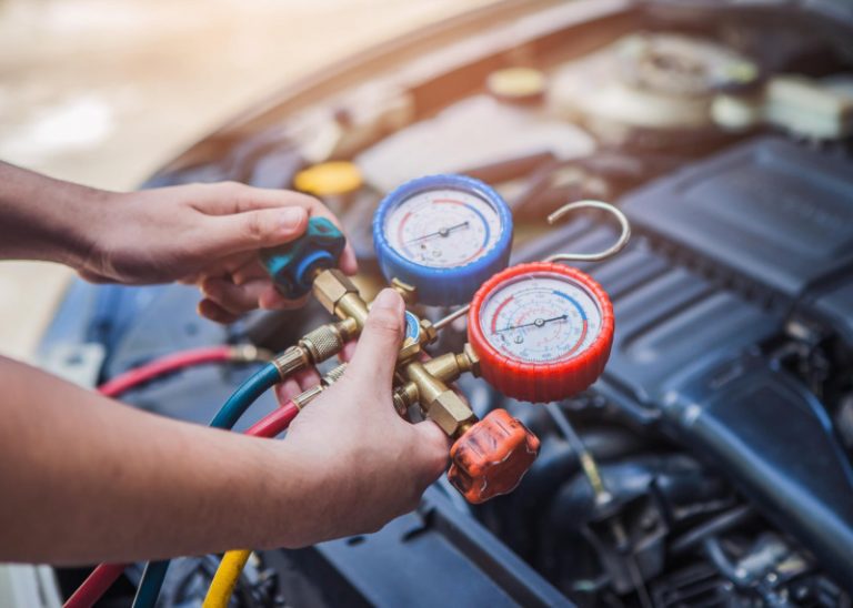
- Check the refrigerant level: You can use AC manifold gauges to measure the high and low-side pressures. Compare your readings to the specifications in your vehicle's service manual. Low pressure indicates a leak or low refrigerant.
- Inspect the compressor: Make sure the compressor clutch is engaging when the AC is turned on. You should hear a click and see the clutch plate spinning. If not, check the compressor clutch relay and wiring.
- Check for leaks: Use a refrigerant leak detector to sniff for leaks around the fittings, hoses, and components. UV dye can also be added to the system to help locate leaks with a UV light.
- Inspect the condenser: Make sure the condenser is clean and free of debris. A blocked condenser can restrict airflow and reduce cooling performance.
Safety – Highlight Risky Components
Working on an AC system involves handling high-pressure refrigerant, which can be dangerous if not handled properly. Here are some important safety precautions:
- Wear safety glasses and gloves: Refrigerant can cause frostbite and eye damage.
- Work in a well-ventilated area: Refrigerant vapors can displace oxygen and cause asphyxiation.
- Never disconnect hoses or fittings while the system is pressurized: This can cause refrigerant to spray out, which can be extremely dangerous.
- Properly recover and dispose of refrigerant: It is illegal and environmentally damaging to vent refrigerant into the atmosphere. Use a refrigerant recovery machine to safely remove the refrigerant from the system.
- Be aware of high voltage components: Some vehicles use electric compressors which contain high-voltage components. Disconnect the battery and follow the vehicle manufacturer's procedures before working on these systems.
- Avoid working on the system if you're not comfortable: If you're unsure about any aspect of the repair, it's best to take your vehicle to a qualified mechanic.
Important Note: Refrigerant is harmful to the environment and must be handled responsibly. Always recover refrigerant using proper equipment and dispose of it according to local regulations. Many auto parts stores will accept used refrigerant for recycling.
Detailed AC Diagram and Explanation
While a written explanation is helpful, a visual aid can be even more effective. A diagram of the AC system helps you visualize the flow of refrigerant and the location of each component. Let's break down what you might find in a typical AC system diagram.
Purpose of the Diagram
A detailed AC system diagram is invaluable for several reasons:
- Repair Identification: Easily pinpoint the location of specific components when performing repairs.
- Troubleshooting: Trace the refrigerant flow to isolate potential blockages or leaks.
- Component Identification: Verify the correct part numbers for replacement components.
- Educational Purposes: Improve your overall understanding of how the AC system operates.
- Customization: If you're modifying your vehicle, the diagram helps understand the impact on the AC system.
Symbols – Explaining Lines, Colors, and Icons
AC system diagrams use standardized symbols to represent different components and connections. Here's a general guide:
- Solid Lines: Typically represent refrigerant lines. Thicker lines may indicate high-pressure lines.
- Dashed Lines: Often represent electrical wiring or vacuum lines.
- Arrows: Indicate the direction of refrigerant flow.
- Colors: While not always used, colors can help differentiate between high-pressure and low-pressure lines. For example, red might represent high-pressure, and blue might represent low-pressure. Consult the diagram's legend for specific color codes.
- Component Icons: Each component (compressor, condenser, evaporator, etc.) is represented by a specific icon. These icons are usually standardized but can vary slightly depending on the diagram's source.
- Pressure Switches: Shown as electrical switches connected to the refrigerant lines.
- Sensors: Depicted as small circles or squares with wires attached, indicating temperature or pressure sensors.
It's crucial to refer to the diagram's legend or key to understand the specific symbols used in that diagram. Don't assume you know what a symbol means – always double-check!
With a solid understanding of the AC system's components, operation, and safety precautions, you're well-equipped to tackle some basic repairs. Remember to consult your vehicle's service manual for specific instructions and torque specifications. Happy wrenching (and stay cool!).
We have the AC system diagram ready for you. Feel free to download it to assist with your repairs!