How To Locate A Key Fob
Let's face it, losing your key fob is a modern nightmare. But before you resign yourself to an expensive replacement, let's explore how to systematically locate it by understanding its underlying technology and common failure points. This article isn't about magically finding your keys under the couch; it's about giving you the technical know-how to diagnose issues and potentially repair a malfunctioning or partially responsive fob.
Purpose of Understanding Key Fob Schematics
Why bother understanding the inner workings of your key fob? Several reasons. First, it aids in
Key Specs and Main Parts of a Key Fob
A key fob, at its core, is a miniature radio transmitter/receiver powered by a small battery. Here's a breakdown of the essential components and specs:
- Battery: Typically a coin cell battery (CR2032, CR2025, CR2016 are common types). Voltage is usually 3V. The datasheet for your specific battery can be found online; this dictates voltage, current capacity (mAh), and expected lifespan. Low battery is the most common cause of fob failure.
- Microcontroller (MCU): The brain of the fob. It processes button presses, encrypts the signal, and manages communication with the car. Specific microcontroller models vary widely, but they generally include an Analog-to-Digital Converter (ADC) to read button inputs and a serial communication interface (like SPI or UART) for programming and diagnostics.
- Radio Frequency (RF) Transmitter/Receiver: This module handles the actual wireless communication. It operates at specific frequencies (e.g., 315 MHz in North America, 433.92 MHz in Europe). The transmitter modulates the signal (often using Frequency-Shift Keying - FSK or Amplitude-Shift Keying - ASK) with the encrypted data. The receiver listens for signals from the car to confirm remote start or unlock commands.
- Antenna: A crucial component for efficient signal transmission and reception. Antenna design is critical for range. Common antenna types include loop antennas, PCB trace antennas, and helical antennas. The antenna’s resonant frequency must match the transmitter/receiver's operating frequency for optimal performance.
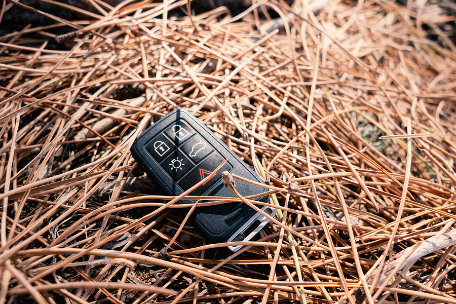
- Buttons/Switches: Provide the user interface for triggering actions (lock, unlock, trunk, panic). These are usually momentary contact switches connected to the microcontroller.
- Encrypted Communication Protocol: This is not a physical component but a vital part of the system. The fob and the car's receiver use a shared secret key and an encryption algorithm to prevent unauthorized access. Common protocols include rolling codes, where the code changes with each transmission, making it difficult for thieves to replay captured signals.
- Circuit Board (PCB): The physical platform that connects all the components. Made of fiberglass or composite material with copper traces acting as wires.
Understanding Key Fob Schematics: Symbols and Conventions
Reading a key fob schematic can seem daunting, but it's just a matter of learning the language. Here's a guide to common symbols:
- Resistors: Zigzag line ( ). Value indicated in Ohms (Ω).
- Capacitors: Two parallel lines ( || ). Value indicated in Farads (F), microfarads (µF), nanofarads (nF), or picofarads (pF).
- Inductors: Looped coil ( ). Value indicated in Henries (H) or millihenries (mH).
- Diodes: Triangle pointing to a line ( ). Arrow indicates direction of current flow.
- Transistors: Various symbols depending on type (BJT, MOSFET). Look for three terminals (base, collector, emitter or gate, drain, source).
- Integrated Circuits (ICs): Rectangular box with numbered pins. Internal functions are usually indicated within the box.
- Ground (GND): Often represented by three horizontal lines getting progressively shorter ( ). Represents the zero-voltage reference point.
- Voltage Supply (VCC/VDD): Indicates the positive voltage supply.
- Wires: Solid lines connecting components. Dots at intersections indicate a connection; no dot means the wires cross without connecting.
Color coding is less common on simplified schematics but may be used on more detailed diagrams. For example, red might indicate VCC, black for ground, and other colors to differentiate signal paths.
How It Works: Signal Flow and Encryption
The key fob's operation can be broken down into a few key steps:
- Button Press: When you press a button (e.g., "lock"), the corresponding switch closes, sending a signal to the microcontroller.
- Microcontroller Activation: The MCU detects the button press and activates the RF transmitter.
- Data Encoding and Encryption: The MCU encodes the command (lock, unlock, etc.) and encrypts it using a pre-programmed encryption key and algorithm. This process often involves a rolling code mechanism to prevent replay attacks.
- RF Transmission: The encrypted data is modulated onto a radio frequency carrier wave (e.g., 315 MHz) and transmitted by the antenna.
- Car Receiver: The car's receiver detects the RF signal, demodulates it, and decrypts the data.
- Verification and Action: The car's computer verifies the received data against its stored encryption key. If the code is valid and the rolling code is within an acceptable range, the car executes the command (e.g., unlocks the doors).
The encryption is crucial to prevent unauthorized access. Rolling codes ensure that even if a thief intercepts a signal, they can't use it later because the code will have changed. The complexity of the encryption algorithms varies depending on the car manufacturer and model year.
Real-World Use: Basic Troubleshooting Tips
Here are a few troubleshooting steps you can take before resorting to professional help:
- Check the Battery: This is the most common cause of fob failure. Use a multimeter to check the voltage. If it's below the specified voltage (usually 3V), replace the battery. Ensure the battery is installed with the correct polarity (+/-).
- Clean Battery Contacts: Corroded battery contacts can prevent proper current flow. Use a cotton swab dipped in isopropyl alcohol to clean the contacts.
- Inspect the PCB: Look for any visible damage, such as cracked traces, loose components, or signs of corrosion. Use a magnifying glass for close inspection.
- Check the Buttons: Test the buttons with a multimeter to ensure they are making proper contact when pressed. A non-functional button can often be replaced with a similar switch.
- Resolder Connections: If you have soldering skills, carefully resolder any suspicious connections, especially around the battery holder, buttons, and antenna.
- Check the Antenna: Visually inspect the antenna for damage. If it's a PCB trace antenna, look for cracks or breaks in the copper. If it's a loop antenna, check for damage to the wire. In some cases, you may be able to improve the range by carefully adjusting the antenna. However, this requires specialized equipment and knowledge.
- Consider External Interference: Strong RF interference can block the fob's signal. Try moving to a different location to see if the fob works there.
- Reprogramming: Some fobs may need to be reprogrammed after a battery change. Consult your owner's manual for instructions.
Safety Considerations
While working on a key fob might seem harmless, there are a few safety precautions to keep in mind:
- Static Electricity: Electronic components are sensitive to static discharge. Use an anti-static wrist strap when handling the PCB.
- Soldering: If you're soldering, use proper safety equipment, including safety glasses and a well-ventilated area. Be careful not to overheat components.
- Battery Handling: Coin cell batteries can be a choking hazard for small children. Keep them out of reach.
- High Voltages: While the fob operates at low voltage, be aware that some components, particularly capacitors, can store a charge. Discharge capacitors before handling them.
- Avoid Tampering with Encryption: Do not attempt to reverse engineer or modify the encryption algorithms. This is illegal and could compromise the security of your car.
Warning: Modifying your key fob could void your car's warranty. Proceed with caution and at your own risk. If you are uncomfortable working with electronics, it's best to consult a professional locksmith or mechanic.
By understanding the key fob's components and how they interact, you'll be better equipped to troubleshoot problems and potentially even repair a malfunctioning fob. This knowledge also empowers you to have more informed discussions with professionals, saving you time and money.
We have a sample key fob schematic file available for download. This file will provide a visual representation of the components and their connections, aiding in your understanding. Please note that specific schematics vary depending on the make and model of your car. However, the general principles remain the same.