How To Make Your Car Ac Cold
So, your car AC is blowing warm air? Bummer. Nothing worse than sweating it out during a summer commute. This article will dive deep into how your car's AC system works and give you the knowledge to diagnose and potentially fix common problems. We’re not just talking about topping off refrigerant; we're getting into the nitty-gritty of the components and their functions. Think of this as your advanced DIY guide to automotive air conditioning.
Purpose of Understanding Your AC System
Why bother learning all this stuff? Well, besides the obvious comfort factor, understanding your AC system empowers you to perform your own maintenance and minor repairs, saving you money. You'll be able to diagnose issues more accurately before taking your car to a mechanic, preventing unnecessary work and potentially inflated bills. Plus, if you're a car modifier or enjoy tinkering, knowing the ins and outs of your AC allows you to make informed decisions about upgrades or modifications.
Key Specs and Main Parts
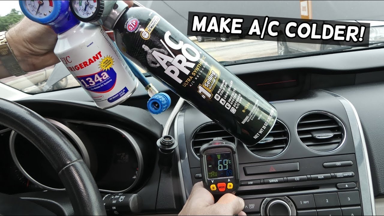
A car's AC system is a closed-loop refrigeration cycle. It uses a refrigerant (typically R-134a or newer R-1234yf, though this article will focus on the generic principles applicable to all) to absorb heat from the cabin air and release it outside. Here are the key components:
- Compressor: The heart of the system. It compresses the low-pressure, low-temperature refrigerant gas into a high-pressure, high-temperature gas. This requires power from the engine, usually through a belt-driven pulley and clutch.
- Condenser: Located at the front of the car, often near the radiator. The high-pressure, high-temperature refrigerant gas flows into the condenser, where it cools down and condenses into a high-pressure, high-temperature liquid. Airflow across the condenser, often assisted by electric fans, is crucial for heat dissipation.
- Receiver-Drier (or Accumulator): This component serves two main purposes. First, it removes moisture from the refrigerant, preventing ice formation that could damage the system. Second, it acts as a reservoir for liquid refrigerant. A receiver-drier is typically used with a thermal expansion valve (TXV) system, while an accumulator is used with an orifice tube system.
- Expansion Valve (TXV) or Orifice Tube: This is the metering device. It reduces the pressure of the high-pressure liquid refrigerant, causing it to expand and rapidly cool. This creates a low-pressure, low-temperature liquid/gas mixture. The TXV is more sophisticated and modulates the refrigerant flow based on evaporator temperature, while the orifice tube is a fixed restriction.
- Evaporator: Located inside the car's dashboard, the evaporator is where the magic happens. The low-pressure, low-temperature refrigerant absorbs heat from the air blowing across it, cooling the air that enters the cabin. The refrigerant then boils back into a low-pressure, low-temperature gas.
- Refrigerant Lines: These are the hoses and pipes that connect all the components, carrying the refrigerant throughout the system.
- Pressure Switches: These switches monitor the pressure within the system. They are safety devices that can shut off the compressor if the pressure is too high or too low, preventing damage.
- Blend Door Actuator: This isn't directly part of the refrigerant cycle, but it's critical for AC performance. The blend door controls the mix of hot and cold air entering the cabin. A faulty actuator can prevent the system from blowing cold air, even if the refrigerant cycle is working perfectly.
Symbols and the AC System Diagram
When looking at an AC system diagram, you'll encounter various symbols and line types. Here’s a breakdown:
- Solid Lines: Represent refrigerant lines. Thicker lines usually indicate high-pressure lines, while thinner lines indicate low-pressure lines.
- Dotted Lines: Often represent vacuum lines or control lines for actuators and valves.
- Arrows: Indicate the direction of refrigerant flow.
- Compressor Symbol: A stylized representation of a compressor, often resembling a pump.
- Condenser Symbol: A series of zig-zag lines, indicating heat dissipation.
- Evaporator Symbol: Similar to the condenser symbol, but typically enclosed in a box to represent its location within the dashboard.
- Pressure Switch Symbol: A circle with a switch symbol inside.
- Color Coding: Some diagrams use color coding to differentiate between high-pressure and low-pressure sides of the system. Typically, red is used for high-pressure and blue is used for low-pressure.
Understanding these symbols will allow you to trace the refrigerant flow through the system and identify the location of each component on the diagram.
How It Works: The Refrigeration Cycle
The refrigeration cycle is a continuous process that relies on the properties of the refrigerant to transfer heat.
- Compression: The compressor, driven by the engine, compresses the low-pressure, low-temperature refrigerant gas. This increases its pressure and temperature.
- Condensation: The high-pressure, high-temperature refrigerant gas flows into the condenser. As air flows across the condenser, the refrigerant releases heat and condenses into a high-pressure, high-temperature liquid.
- Metering (Expansion): The high-pressure liquid refrigerant flows through the expansion valve (TXV) or orifice tube. This component restricts the flow, causing a significant pressure drop. As the refrigerant expands, it rapidly cools, creating a low-pressure, low-temperature liquid/gas mixture.
- Evaporation: The low-pressure, low-temperature refrigerant enters the evaporator core. The blower motor forces air across the evaporator fins. The refrigerant absorbs heat from the air, causing the air to cool down and the refrigerant to boil back into a low-pressure, low-temperature gas.
- Return to Compressor: The low-pressure, low-temperature refrigerant gas returns to the compressor, and the cycle repeats.
The entire system is designed to continuously circulate the refrigerant, removing heat from the cabin and dissipating it outside.
Real-World Use: Basic Troubleshooting Tips
Here are a few common issues and how to troubleshoot them:
- No Cold Air: The most common problem. Start by checking the refrigerant level. You can use a manifold gauge set to measure the high and low side pressures. Low refrigerant is a common culprit, but it’s often a sign of a leak. If pressures are within spec, check the compressor clutch. Is it engaging when the AC is turned on? If not, the clutch could be faulty, or there could be an electrical problem. Finally, consider the blend door actuator. If it's stuck, it might be blending in hot air, even when the AC is on.
- Weak Airflow: Could be a clogged cabin air filter. Replacing the filter is a simple and often overlooked maintenance item. Also, check the blower motor and resistor. A faulty resistor can cause the blower motor to only work on certain speeds or not at all.
- Strange Noises: Grinding or squealing noises could indicate a failing compressor or a worn belt. Hissing sounds could indicate a refrigerant leak.
- AC Works Intermittently: This can be tricky. It could be a faulty pressure switch, a failing compressor, or even an electrical issue. Monitoring the system with a scan tool while the problem is occurring can help pinpoint the cause.
Important: Before performing any repairs, always disconnect the negative battery cable to prevent electrical shocks.
Safety: Highlighting Risky Components
Working on an AC system involves handling high-pressure refrigerant, which can be dangerous if mishandled.
- Refrigerant: Never vent refrigerant into the atmosphere. It's harmful to the ozone layer. Always recover refrigerant using a dedicated recovery machine before opening the system. Refrigerant can also cause frostbite if it comes into contact with skin. Always wear safety glasses and gloves when working with refrigerant.
- High Pressure: The high-pressure side of the system can reach extremely high pressures (hundreds of PSI). Never loosen or disconnect any fittings on the high-pressure side while the system is charged. Doing so could result in a dangerous refrigerant release.
- Electrical Components: The compressor clutch and blower motor are powered by electrical circuits. Be careful when working with these components to avoid electrical shocks. Always disconnect the battery before performing any electrical work.
- Sharp Fins: The condenser and evaporator fins can be sharp. Wear gloves to protect your hands.
Working on a car AC system can be complex and potentially dangerous. If you are not comfortable performing these repairs yourself, it is best to take your car to a qualified mechanic.
We have a detailed AC system diagram available for download. This diagram provides a visual representation of the system and can be a valuable tool for troubleshooting and repairs. Contact us, and we'll send you the file.